PCB stencils make application of solder paste a snap, but there’s a long, fussy way to go before the paste goes on. You’ve got to come up with some way to accurately align the stencil over the board, which more often than not involves a jury-rigged setup using tape and old PCBs, along with a fair amount of finesse and a dollop of luck.
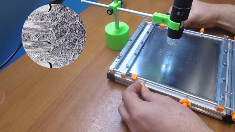
Luckily, [Valera Perinski] has come up with a better way to deal with stencils. The Stencil Printer is a flexible, adjustable alignment jig that reduces the amount of tedious adjustment needed to get things just so. The jig is built mostly from aluminum extrusions and 3D-printed parts, along with a bunch of off-the-shelf hardware. The mechanism has a hinged frame that holds the stencil in a fixed position above a platen, upon which rests the target PCB. The board is held in place by clamps that ride on threaded rods; with the stencil flipped down over the board, the user can finely adjust the relative positions of the board and the stencil, resulting in perfect alignment. The video below is mainly a construction montage, but if you skip to about the 29:00 mark, you’ll see the jig put through its paces.
Granted, such a tool is a lot more work than tape and spare PCBs, but if you do a lot of SMD work, it may be worth the effort. It’s certainly less effort than a solder-paste dispensing robot.


Per his other videos, this guy obviously ‘eats his own dogfood’; that is, he actually uses the tooling that he makes.
Woof.
A nice project and very well executed.
What I liked about the video were all those brightly colored tools that were used.
Cool project, very usable!
Has everyone forgotten about Stencil8? http://www.hoektronics.com/2012/10/27/super-simple-smt-stencil8/
You can buy jigs on aliexpress (for not much) for screen printing, which have the appropriate clamps and screws to do this with framed solder stencil screens. I’ll never order unframed stencils again – far too fiddly.
This project looks fun, and I would have used it in the past, but not now.
I really don’t get the issue. With unframed stencils I frame up the board on all sides to have paste applied with scrap circuit boards of the same thickness, secure them with tape, align the stencil once, tape down one edge securely, and then apply paste, flip up stencil, remove board, put a new board down, apply paste, etc. Never had a problem, not down to 0.5 mm pitch pads, and you can paste bunches of boards really quickly this way.
That being said it’d be an issue if the board wasn’t square, or at least easy to frame out, but those cases are rare for me, at least.
I like to order stencil which have the same size as the PCB – if it’s single sided. And one side double the length if the PCB is double sided.
This has for manual printing the following advantage
– 3 sides can be used to align the PCB and stencil, then I press them together with a vice – keep some space for it in the design of possible.
– stencil of the original size or even worse have at least at jlcpcb a far more expensive shipping costs. Small stencil of the size of the PCB are far cheaper.
I’ve seen several people on youtube using an old credit card to apply the paste, and getting poor results.
I recommend using a stainless steel putty knife instead. Get yourself a cheap set with different widths.
Also, the angle should be around 30-45 degrees, and the paste should be applied in a single sweep, leaving a mostly clean stencil behind. If there are thick remnants of paste on the stencil, most likely the paste is old and dry. I suspect that some cheap Chinese sellers online are selling expired paste as new.
If the paste is runny, try applying it cold. Make sure it’s mixed well.
If you go over the board more than once, the repeated pressure and small up and down motion will tend to squish the paste between board and stencil. Also, if there’s any sideways motion, it will smear the paste.
In my experience, the trickiest parts are fine pitch connectors, followed by QFP parts. Generally you get better results if you don’t copy the paste layer from the copper pads, but if you make the paste apertures slightly smaller. Aim for 80% paste coverage, or use recommendations from data sheet. You also want to reduce paste on big pads underneath components, such as QFN. Aim for less than 50% coverage on those, otherwise the layer gets too thick and the part will start to float during reflow.
This is exactly how the alignment system on a vintage DEK 265 Screen Printer worked back in 1995. Two X servos and one Y servo gave you X. Y, and theta adjustments automatically with the fiducial camera system. Nice to see it implemented in a manual setup for DIY, although there are several manual screen printers on the market that work the same way. Check out the Manncorp RT2100 https://www.manncorp.com/rt2100-manual-smt-stencil-printer.html