It’s no secret that we here at the Hackaday are suckers for cool display. LEDs, OLEDs, incandescent, nixie or neon, you name it and we want to see it flash. So it fills us with joy to discover a new way to build large, daisy-chainable 16-segment digits, and even more excited to learn how easy they are to fab and assemble.
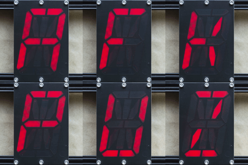
A cousin of the familiar 7 segment display, the 16 segment gives so many more possibilities (128% more possibilities to be exact) for digit display. To be specific, those extra segments unlock the ability to display upper and lowercase latin characters as well as scads of punctuation.
But where the character set is complex, the assembly is anything but thanks to a great design from [Kolibri] called klais-16. They’re available fully assembled if you want to jump straight to code, but thanks to thorough documentation (seriously, check this out) assembly is a snap.

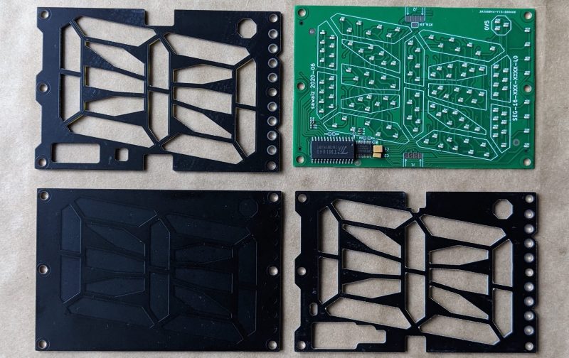
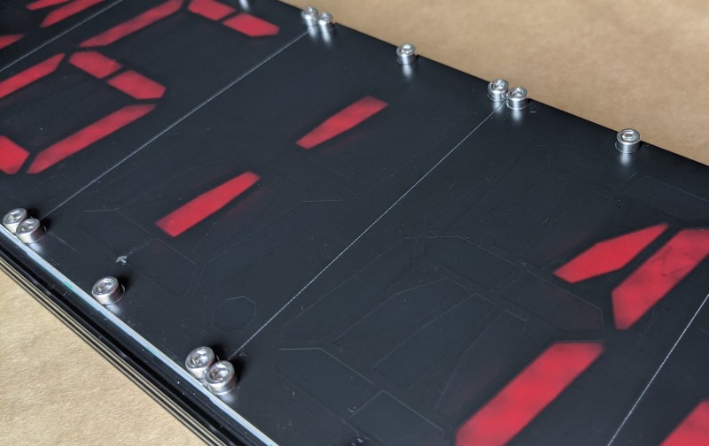
 Each module is composed a very boring PCBA base layer which should be inexpensive from the usual sources, even when ordering one fully assembled. A stackup of three more PCBs are used for spacing and diffusion with plans for die-cut or injection mold layers if a larger production run ends up happening. Board dimensions for each character are 100 mm x 66.66 mm (about 4″ x 2.5″). Put together, each module can stand on its own or be easily daisy-chained together to make a longer single display.
Addressing all those bits with an elaborate, ugly control scheme would be a drag but fortunately the firmware for the onboard STM8 microcontroller exposes a nice boring serial interface which can be used without configuration to display strings. There’s even an example Windows Batch script!


Not a hack… It’s far too professional for that. One of the best thought-through and finished projects I’ve seen on here for a long time.
True but OpenSourceHardwareADay just doesn’t roll off the tongue does it?
or you could call it OSHaDay, which is less of a pain
Certainly one of the better done ones but not surprising as they are trying to sell the things
Nicely done, but the number of the LEDs for each segment seems a little off. There are only 7 LEDs each for the biggest segments on the right side, while there are 16 total for the top segment. You can already see the difference in brightness in the animated GIF above.
The schematic doesn’t match their board placement. Schematic calls for 16 segments of 8 LEDs each, but the board has two more segments- the decimal point and an underline.
“128% more, to be exact”? Huh?
🤣 indeed. huh?
i would be ok with 512 times more possibilities i think
16/7 = 2.28, or 16 segments is 128% more than 7 segments.
Except it says “the 16 segment gives so many more possibilities”. So what you really need to do is (16^2 – 7^2) / 7^2 = 422% more possibilities.
i think you mean (2^16 – 2^7) / 2^7 = 2^9 – 1 = 511%
Nowadays it’s probably cheaper to buy off-the-shelf TFTs than custom-made 16-segment displays.
This! This is the reason I always read the comments on Hackaday, as this is something I want to try! And you’re probably right about the price point of view. I do like the matt finish of the non-light-emitting parts of the display. But what is stopping me to create a mask to mount on top of the TFT-display and only show 16 segments?
It has FCC Id 000000 printed on the board. Afaik there is no self certification for FCC. Can someone explain?
Whats with all these fake certificates printed on the circuit board and schematic? Makes me angry..
My favorite is seeing the old “QC PASS” sticker (which generally means that the sticker passed quality control) replaced by silkscreen.
That is called a placeholder for a future officially assigned fcc number.
Honestly, LED matrix panels make more sense at this point.
Looks good. I disagree with the comments suggesting using TFT screens.
This is much simpler and potentially much cheaper.
I hope they document the process for obtaining certification.
And also would require significantly less RAM to store the display and sounds like it is super simple to interface to.