“Time-domain reflectometry” sure sounds like something that needs racks of expensive equipment to accomplish. In reality, TDR is just measuring the time between injecting a pulse into a cable and receiving its echo, either from the other end of the cable or from some fault or defect along the way. It’s a useful technique, and as [Allen Wolke (W2AEW)] shows us, it can be accomplished with little more than a battery, a resistor, and an oscilloscope. And a little math, of course.
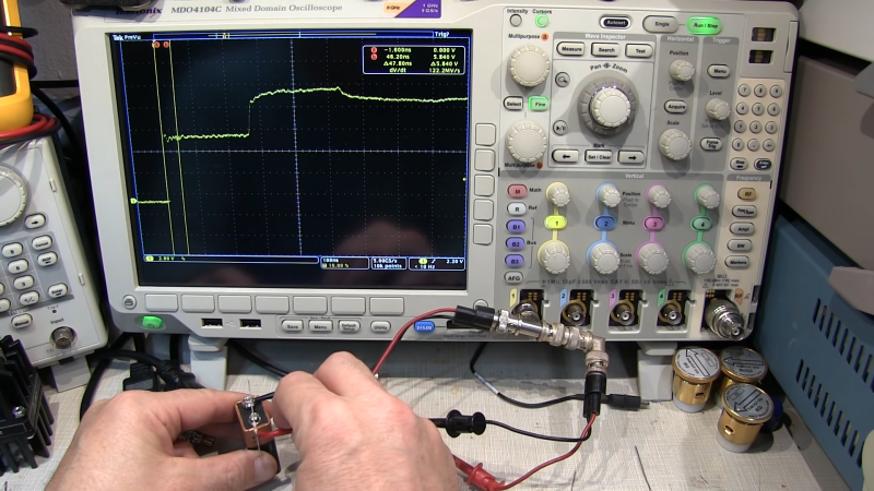
There are, of course, dedicated time-domain reflectometers, but all of them are really just elaborations of the basic principles [W2AEW] demonstrates with his simple setup. The oscilloscope is set up with a tee connector on one channel; one side of the tee is connected to the cable under test, while the shield conductor of the other side is connected to the negative terminal of a 9V battery. A resistor connected to the center conductor is used to complete the circuit, which sends a brief pulse down the test cable. The scope is set up to capture the outgoing pulse as well as the return pulse, allowing the time between the two to be measured. Some simple math gives the length of the cable, the distance to a fault, or with a little rearrangement, the velocity factor of the cable.
The video below shows the simple method at work on coax and Cat 5e Ethernet cable. It even worked on a roll of zip cable, which was a little surprising. If this technique is too simple, you can always elaborate a bit and roll your own TDR tester. Googly eyes optional, of course, but recommended.


Very interesting and informative :-)
That is the best TDR video I’ve ever seen, though I’m rather embarrassed I didn’t think of doing that. Just not digital enough in my idea of a scope.
A mercury wetted relay reed would give a more reliable switch transition and be *almost* as simple, but that was not the purpose of this video. And the search for a mercury wetted relay prevented my doing it for many years.
Here are some examples of TDR using a Tek 11801 & various 20 GHz sampling heads.
https://www.eevblog.com/forum/rf-microwave/testing-rf-connectors-and-cables/msg2640531/#msg2640531
It’s a great way to test RF connectors. It more than justifies building or buying a fast edge pulser. You’ll need a DSO which is higher than the maximum frequency of interest. But for HF QRP work a 100-200 MHz DSO is more than enough.
With modestly better front end and FW designs we could do 4 GHz on cheap HW using sampling scope technology (you can’t escape the need for a very fast sample and hold circuit. Not easy!)
Is this relay really faster than a MOSFET with a suitable driver?
Orders of magnitude faster with no bouncing.
Hi, thanks for your nice video. I was trying to use the setup to
1. find a breakage within a 30m shielded cable
2. measure Velocity for a BNC cable of known length.
I did not succeed. I think I reproduced your setup and I see the first voltage step, but I do not see the reflexion / second step… I have of course tried to vary the time scale.
Any ideas?
Also, could you explain why it will not work with a single cable without shield/twisted pair?
Thanks a lot!
> 1. find a breakage within a 30m shielded cable
3×10^8m/S is 3.33×10^9S/m times a velocity factor of 70% is 2.33nS/m, 30cm would be 700pS. If I’m figuring this correctly, you’ll need a scope that is good to at least 2GHz, just to start being able to detect the return pulse, if and only if your pulse generator has a risetime considerably shorter than 700pS (7×10^-10 seconds).
But that only gets to where you can just detect the end of the cable. Detecting a break would mean a much shorter time.
> 2. measure Velocity for a BNC cable of known length.
> I did not succeed. I think I reproduced your setup and I see the first voltage step, but I do not see the reflection / second step… I have of course tried to vary the time scale.
> Any ideas?
To measure the length, the cable MUST be mismatched. The simplest way is to leave it open or shorted. Did you do that? Subject to the same limitations above.
> Also, could you explain why it will not work with a single cable without shield/twisted pair?
It relies on the smooth impedance curve of a transmission line so there is only one reflection at the impedance discontinuity.
Imagine this: I shoot a wave down a long ditch closed at the end. It hits the closed end and reflects back as a fairly compact wave.
Now imagine I shoot a wave down a long ditch that is narrow at my end, and funnels out increasingly wider the further it gets away from me. Virtually nothing will reflect back. In fact, this is the design of some antennas.
With an open or short on the opposite end of the cable, you’ll see it bounce back and forth and eventually stabilize at the driving voltage after having bounced up and down repeatedly.
This is what SWR is: standing wave ratio. If you put a sine wave in, instead of a step pulse, you’ll see the reflection add and subtract from the sine wave being applied, so that some spots have no detectable voltage, and others have very high peak voltage.
Hi, thanks for your reply. I think you misread but still got a valid point 😂
In reality I want to measure a cable of 30 meters not cm, so that should help, but for testing the method I used a much shorter cable, so probably it was too short…
If I understand you correctly I cannot resolve the two steps if the cable is too short… can I check this assumption by checking the “height” of the voltage step – which should be higher than the “incoming battery voltage” ? I used a 9V battery and observed a slightly higher voltage step – but around 10V… far from double… does this make any sense? Sorry for my English, I’m out of practice…
We (my fellow teachers and I) were actually thinking of trying to make Standing waves with your method by using a wave generator instead of the battery… haven’t tried, yet, since I did not even manage your setup
Thanks a lot!
I have no idea how I read 30cm when it clearly says 30m…
Divide everything I said by 100 regarding frequency, then, and multiply by 100 for time.
The battery itself is a low resistance load to the voltage coming back.
If the cable is 50 ohms, put a 50 ohm resistor in series with the 9V battery. You should then see about 4.5V going out, and 9V coming back.
I’ve seen it done with a TTL oscillator, which may be more complicated than a switch, but really isn’t complicated in itself.
I’ve done it with the Oscilloscope’s 1KHz calibration output, only a resistor required.
Use to do it on the old analogue scopes. No storage required.
Used to do it with tape measure. No scope required.
Exactly what I was thinking.
Very good content, did something pretty similar a few years ago with esp32 as pulse generator and oscilloscope, using knowledge and lab materials from university time
Must not use lead acid batteries for this. Their high mass dialates time at the input end :)
Have lead acid batteries become a HaD meme? :-o
only if you combine it with a 555, Arduino or a raspberry pi of course. Duh…
I have used the optical version of this, it is very handy for knowing when and where someone has been messing with your fibre optics.
“handy for knowing when and where someone has been messing with your fibre optics” s in detecting break in the cladding on submarine fibre-optik data cables- brazil to portugal- Lajes air base?
Great, practical go thru. Thanks for including the FAQ regarding single conductors too. I love that there are so many high quality videos to explain stuff like this to my colleagues so I don’t have to setup the lab to show them. Thanks again!
i’m still novice about this sort of stuff and i thought to myself that i understood it but really it just raises more questions!
my first thought is that the cable basically acts like a capacitor, it conducts an infinite current (dead short) for an instant because the whole thing starts out discharged, which pulls the voltage down because the resistor only lets a small current through. then the wavefront hits the end of the capacitor and now the whole thing has some charge on it and its current draw decreases rapidly.
but what i don’t understand is, wouldn’t the capacitance of the cable have an effect separate from the length of it? once the wavefront reaches the end, there is no longer any part of the capacitor that is infinitely conducting but all of it would still be somewhat conducting? i haven’t even attempted any of the math, is the difference between the capacitor charge curve and the duration of the short just so significant that it looks like a discrete transition instead of a curve?
i just kind of have this intuitive expectation that after the wavefront reaches the end of the cable, it will switch from the low state to a capacitor-charging RC curve. i guess the RC constant is so short that it looks like a discontinuity??
This is a wave phenomena. Don’t think of it as charging a capacitor but more as an empty water channel in which you inject a sudden flow of water. The water front moves to the end of the channel where it bounces (reflects). As there is still water coming in, it has no other way then to travel back *on top* of the inflowing water. So if you take continuous level measurements at the beginning of the channel you get first a steep rise as the flow starts, followed by a time where the level stays the same. Then suddenly the level will rise to twice its initial steady level as the first water is coming back at you (at which point it is time to duck).
That is a great analogy.
With your hand on the longish wire, the rise time can’t be wonderful, which will really limit the length of cable you can test. You need harmonics to overcome the distributed reactance of a long cable.
Or do multi-kilobuck TDR pulse generators use SMA connectors and ultra-short conducting paths just as a reason to charge multi-kilobucks?
Still, a cute and educational hack!
Anything under about 3 meters is hard to reliably see on a TDR. Sometimes you can add a length of cable between the tester and the faulty cable. To see close in faults.
Its a handy way of doing it prefer a logic gate though…must admit when I saw this on YT I figured it would be up here soon enough ..lol
The best stimulus source is the fibre ethernet optical laser driving circuit. Sharp short pulses and can shoot them at any rate you could wish for.
It would be interesting to squash the horizontal display a bit to see how long the elevated return level stays up.
Going to try this although I have an analog scope so it’s going to need repeated pulsing
Hi, just discovered this – looks to be a genius way to locate a break in a cable. I’m going to try it on some balanced microphone cables. If it works for me I’ll make up a dedicated XLR connection adapter. Can’t think why I’ve never thought to try this before. Thankyou.