
Recently, I was offered a 1997 Volkswagen Golf for the low, low price of free — assuming I could haul it away, as it suffered from a thoroughly borked automatic transmission. Being incapable of saying no to such an opportunity, I set about trailering the poor convertible home and immediately tore into the mechanicals to see what was wrong.
Alas, I have thus far failed to resurrect the beast from Wolfsburg, but while I was wrist deep in transmission fluid, I spotted something that caught my eye. Come along for a look at the nitty-gritty of transmission manufacturing!
Lumps And Bumps
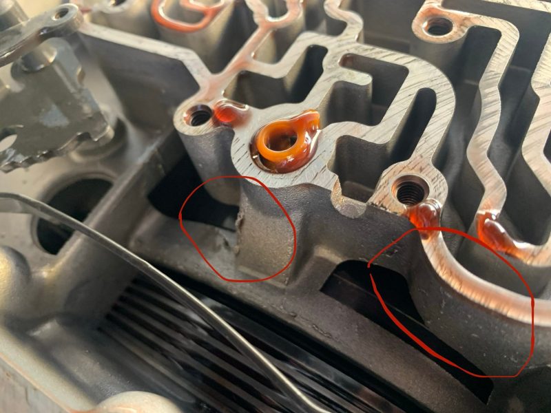
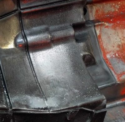
With the transmission pan dropped and filter removed, I had a clear view of the internals of the transmission case. As a former casting engineer, certain elements of the finished part stood out to me. Various parts of the housing featured little bumps and protrusions — chunky pimples on what were otherwise flat surfaces or smooth rounded edges. These were matched by what appeared to be a series of fine crack-like patterns on the surface. These defects are evidence of imperfections in the surface of the die, suggesting the tooling is pitted and cracked where it should instead be smooth.
The area affected was not a machined section, merely acting as a fluid reservoir. Thus, the anomalies have no real effect on transmission performance. However, their presence does tell us a little bit about the state of the tooling used by Volkswagen to produce the castings. A brand new die fresh from the toolmaker does not typically produce parts with cracks, pits, and lumps evident on the surface. The rough nature of the 01M transmission housing in my 1997 Golf is evidence that Volkswagen was running its casting dies well into the tens of thousands of shots, perhaps even into the six figures. Given the nature of the features, which are due to the die’s inherent physical condition, they’re not a one-off fault on a singular casting. Instead, line engineers and operators would be aware that the die is aging and becoming worn. Given the flaws occurred in a non-crucial location, a conscious decision was likely made to ignore the flaws and ship the parts, given they were unlikely to be noticed by the average driver who doesn’t disassemble their transmission to kill some time on the weekend. Similar flaws in a visible or functional area might instead be “fettled”, where the offending protrusions are ground off by a human operator or a machine.
Given the defects cause no functional impediment to the transmission, one can understand the decision to pass the parts in the interest of keeping costs low. However, to understand how the defects happened, let’s take a little crash course in high-pressure aluminium die casting.
A Primer On High Pressure Die Casting
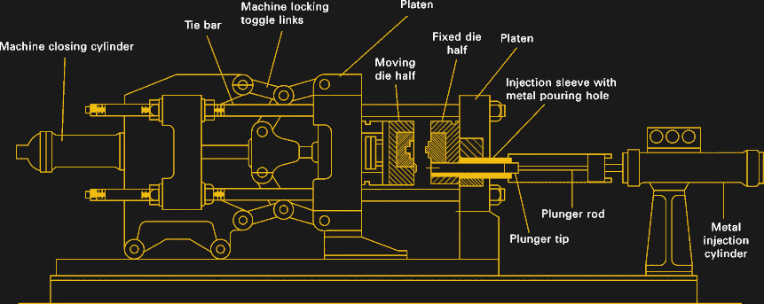
Modern transmission cases are often manufactured using the high-pressure aluminium die casting process. This process involves huge metal moulds, called dies, that come in two halves and are pressed together, creating a cavity between the two. Usually, vacuum is then applied to suck air out of the die cavity to reduce gas entrapment. Next, molten aluminium is poured into a cylinder, and a piston is used to inject the aluminium into the die cavity at very high pressure. Each time the piston fires molten aluminium into the die, this is called a shot.
By injecting molten metal under high pressure, it reduces the problems caused by the aluminium shrinking as it cools. This shrinkage can cause voids in the final product, referred to as shrinkage porosity. Keeping the pressure high ensures the dies are fully filled with as much aluminium as possible and reduces the amount of shrinkage of the final part. To resist the high pressure of the shot, the two halves of the die are held together with a special locking mechanism that is supposed to keep the die shut and stop metal leaking out around the seams where the two meet. Of course, if the dies aren’t perfectly flat or aligned properly, sometimes metal escapes around the seams, called flash, which is where you may see a small parting line on a finished part. In extreme cases, some flash escapes the die entirely, and this is very scary the first time it happens on your shift. Typically, the line operators will chuckle heartily as you are startled by the stinging metal.
Shots, Shots, Shots, Shots, Shots!
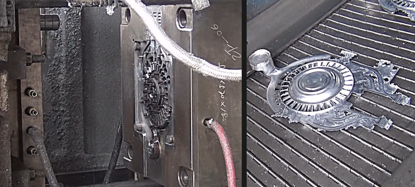
In the same way we track the miles travelled as an estimate of wear on an automobile, die casting machines track the number of shots made. Every cycle of filling the piston, injecting aluminium into the die, and removing the part puts wear on the machine and the dies themselves. Dies weigh many tons, and are constructed of high-strength tool steels. A die may cost many hundreds of thousands of dollars to produce, and thus must pay for itself by producing tens of thousands of parts. Engineers work hard to ensure dies last as long as possible in order to run a cost-effective casting operation.
A typical die may last over 100,000 shots with regular maintenance and repair. But over time, the wear and tear can become too much, and the die must be replaced. There are many ways a die can fail to produce quality parts; a full run down would fill a hefty textbook, and is beyond the scope of this article. Instead, let’s look at the causes of the cracks, lines, and bumps we found on our Volkswagen 01M casting.
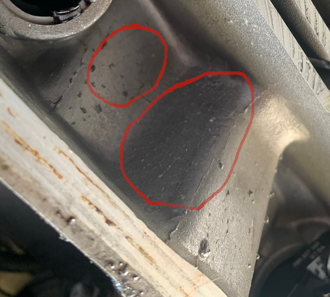
Cracking of the die surface and the resulting defect on the part surfaces is typically referred to as heat check. When the hot liquid metal is injected into the die, it hits certain surfaces in the die before others. These areas of the die heat up more than their surroundings, and undergo greater thermal expansion and contraction with each shot of molten aluminium. These cycles cause cracking and damage over time. The cause is thermal, hence the name. Repair is possible by polishing back the cracked surfaces of the die, or by welding fresh metal onto the die and grinding back to the original profile. However, such a repair does not treat the root cause, and heat check will reoccur as it racks up further shots.
Pitting of the die tends to be caused by cavitation. As hot metal flows into the die at high speed, tiny bubbles or pockets of vacuum can form and then collapse. This happens in specific areas due to the nature of the fluid flow through the die cavity. Typically, it’s in a region where the flow direction changes or encounters an obstruction, and a low-pressure area is surrounded by high pressure liquid metal. As the pressure increases around the low-pressure bubble, it eventually collapses. The collapsing bubble can generate an intense shockwave and localized high temperatures, damaging the surface of the die. This starts on the microscopic level, but over time, the damage increases and the pits grow deeper as the number of shots made on the die increases. Similar to heat check, the damage can be repaired by welding fresh metal to fill the pitted area. But without redesign to the die geometry to reduce the cavitation problem, it’s not a permanent solution and the damage will reoccur.
The damage to the dies evident on our finished transmission housing is understandable in context. The 01M transmission was used in a multitude of Volkswagen vehicles in the 1990s and early 2000s, ending up in hundreds of thousands, if not millions of cars. Volkswagen likely had multiple casting machines running round the clock with many dies on hand to pump out the necessary parts over the years. Some wear is to be expected at these high production levels. Given that the anomalies spotted were in a non-functional location, the engineers would have cleared the parts to flow down the line while monitoring the die’s condition for further problems.
Hopefully this article has taught you a little something about how high-pressure die cast parts are made, and will enable you to smartly show off to your friends next time you’re at the junkyard. For those interested in process control, fluid mechanics, and manufacturing efficiency, die casting can be an interesting field to work in. The world loves aluminium parts, so the skills you learn should serve you well into the future!


Aren’t some VW gearboxes made from magnesium, and when people throw them on a bonfire…WHOOSH!!!?
Have you tried setting fire to a solid block of magnesium? Thin shavings will burn but not a solid hunk of metal.
I wouldn’t put too many bets on that logic :P once magnesium reaches a critical temperature it will rapidly oxidize happily with what ever donor oxygen is readily available.
https://www.youtube.com/watch?v=mLt0cToM_vw
Just one such example
and why you don’t put water on any such fire
https://www.youtube.com/watch?v=kEN-h5FN3yk
Well, Volkswagen made a pretty big bet on that, and I don’t remember hearing any widespread cases of their engine cases bursing into metallic flame.
Totally disagree here. In fact, I have MAPP gassed a magnesium chunk but it won’t ignite. I drop a single drop of water on it and BOOM it catches brilliantly.
That isnt magnesium?
should be aluminium die casting.
Doesn’t look like Magnesium!
Long time ago I did have a car whose manufacturer original tire rims were not made of aluminium but instead were made from diecast-magnesium (Mazda 626 GE). And what should I say: I did scratch the rims but neither could you burn the rims nor did the scratched rims oxidize that much.
As moiaeg said totally right: A solid lump of it won’t burn, very much like your car’s steel parts won’t burn either. BUT on the other side: If you would take Iron filing flakes or even dust from sanding some iron parts, those WILL burn. Same for pure Magnesia. But both, my example of my tire rims AND the VW die-cast-parts of this gearbox are NOT pure Magnesium but alloy of multiple metals. It may be some alloy of Magnesium, Aluminium Zinc, sometimes you can also find alloy with Magnesium and Sillicium.
If you file down some flakes of it so it gets a big chemical active surface where the metal can react with oxygen from the air then it will at least corrode very fast, in extreme cases and with some heat as starter energy it will even burn or explode. If you blow fine dust of iron or magnesium into a flame the dust may explode…
But hopefully your car won’t consist of this dust, does it? ;-)
You’re incorrect – I’ve personally tossed a NewProcess transfer case half into a burn pile after it reached temperature, it did indeed burn.
Magnesium alliys and not pure magnesium is used in such parts manufacturing and won’t go on fire.
A BLOCK OF PURE MAGNESIUM WILL GO ON FIRE QUITE EASILY.
Lighting a magnesium casting (or any reasonable size hunk of magnesium) is actually pretty hard- the metal conducts heat well. and will only burn when it is above the melting point of the metal. Yes, putting a magnesium casting on a big enough fire will eventually create an “extreme exothermic reaction” but it will take a while- it isn’t anything instant- this is why you need to use filings or metal ribbon for firestarting.
My Dad used to bring home magnesium printing plates from his job that were roughly 3″ x 4″ x 0.5″ thick. He had very little trouble lighting them with his cigarette lighter.
I don’t doubt that it can and will burn in the right conditions. Everything that I’ve seen (including personal experience) has shown it is harder than (I) expected. A magnesium firestarter block I set under a 40″ Fresnel lens in the summer sun– adjusting regularly (while wearing welding goggles)- I couldn’t get the damn thing lit. A big differentiator for materials used now, particularly for casting, is the alloy. If I read the wikipedia article correctly- the FAA is allowing the usage of some current alloys in aircraft cabins.
It seems that the popular opinion of Magnesium is that it just takes a spark, and its all over- the whole thing goes up. True, water is the wrong thing to use to put out a Mg fire, but magnesium is a great metal for a lot of purposes, casting included.
Not just aircraft cabins: Electrical generators have been made from magnesium alloy for decades, and that’s a critical use case because a generator can KO the entire engine. I’ve seen them not burn despite some horrific heat generation. I guess it’s down to the exact choice of alloy.
A plasma cutter torch does the job well :)
The engine cases of aircooled VW’s were made from AS91. Some of the transaxles may have been as well. I made it a point to keep a specialized fire extinguisher on hand when machining it. Never had much luck setting off sizeable pieces but the chips went up fairly effortlessly and rather impressive.
Until the Rangers cracked down, many “End Of Life” VW engine cases were tossed onto a large sand dune bonfire.
Whoosh..
So yes, they do burn with light and fury.
The second question is, how does VW mass produce such a precision item quickly.
Cast the cases, and rough cut on the CNC.
The real precision is, the metal parts inside. Crank, cam, gears for the trans axle.
After the rough cut, the precision part is measured. The the difference between the gear stack and the inside of the case is the “Shim Stack” added to the gearbox to create the total package with precision.
Years ago VW had a video explaining the process, but I’ve not seen it for years.
And yes, I’ve built a few hundred VW trans axles.
old veedub crankcases will light up a entire desert valley
Are you thinking of Zaporozhets ZAZ-966-8? both magnesium gearbox and motor, leading to Soviet Bloc Formula 1 clone called Formula Easter using ZAZ-966 gearboxes due to lightness. Fun fact, gearbox was mounted backwards from its original intended ZAZ position meaning gear positions were also reversed.
They are not mad of magnesium, they are made of an alloy including magnesium. And that was only on some of the older beetles.
“The world loves aluminium parts, so the skills you learn should serve you well into the future!”
Anyone doing high-pressure at home?
You’d need tens of thousands of dollars, I reckon. But for those who get involved in the industry, I don’t see the demand for their skills going away anytime soon.
That said, I’d recommend against trying to pursue the career in Australia. Our manufacturing sector is dying.
Great to see an article from a fellow Australian! Very well written and interesting.
I think that ‘Dutch disease’ from exporting minerals has pushed our exchange rate too high for manufacturing to be viable. As well as the sky-high wages.
I was wondering why the cast has to be so big and heavy when the parts are only little? Is it to stop it heating up too much?
Wouldn’t call Australian wages “sky high”, they’ve been flat for 30 years. Only in comparison to countries that have widespread poverty.
Aren’t the blemishes you see typical of sand castings? (or maybe shell moulding?)
I used to be in Q.C. on a green sand line for cast (gray) iron. The surface finish in these pictures looks much different than I am used to with a sand casting.
My guess is the tool steel (D2 steel? who knows) used for the die suffered damage from gas bubbles, corrosion, impurities in the aluminum, or the flow of the aluminum. It does look a bit like a mark from a cold weld, but that might be a coincidence, I’m not sure aluminum could stick to steel firmly enough for that to occur. Maybe some beads of slag or debris from the pump machinery was mixed with the melt and was carried along for the ride into the die. That’s potentially a very expensive mistake.
For cheapness, cast iron is fantastic. You get pretty good results and the pattern (it’s like a die) cost is almost 100% labor and 0% material. We used to make them out of wood back in the old days. Anything that holds its dimensions when rammed into damp sand will do the job.
I agree that it does not look exactly like sand/iron castings. And I acknowledge that the author has done this sort of inspection as a job so is more likely to be correct than I am.
In fact the only thing that set me off down that line of thought was that I don’t think that the part could have come out of the die if the lumps in the first picture corresponded to holes in the die wall.
I have not done, or been involved in, any shell moulding production, but mentioned that as a process that might give an appearance intermediate between sand and die casting.
I have done a fair bit of pattern-making for reproduction parts for machine tools and veteran vehicles. 3D-printing has made the production of core-boxes and loose part patterns _much_ easier.
(As an example, here is a 3D printed pattern for a lathe fixed steady (red) with a support piece (black) to be removed after moulding the first half https://photos.app.goo.gl/o3oQhphGQpaXUn4W6 )
Funnily enough Andy, when I first spotted these anomalies, I hung back for a second. I had to make sure I wasn’t about to embarass myself in front of the entire global casting community by confusing a sand-cast part for die cast.
You’re right that some of those little lumps and bumps look like they could come from a dodgy sand cast mould. However, such damage is common on high-pressure casting dies too. The aluminium doesn’t really stick to the tool steel of the die so they still extract fairly easily.
The way you know this part is definitely high-pressure die cast though is the heat check; that’s a surface feature you wouldn’t ever see in a sand casting.
Impurities in cast iron….
Worked at a company that used to sand cast, then machine. They would sweep up and re-cast all the scrap. One operation was an 8″ face mill with carbide inserts. Broken inserts ended up in the melt, and got cast. Along with the broken inserts…. there is a lesson there….
I didn’t know I wanted to know this about casting Aluminium, but now I do…
I’m doing what I always do when I leatn something, I’ll se if there is a youtube video of it…
6 hours later you are watching a tutorial about how to talk to giraffes….
Ooh! Talking to giraffes… and the circle continues.
Only nitpicking, but “used by Volkswagen to produce the castings”: I don’t think VW every produced these. As far as I remember they were made by some component supplier.
VW and audi did produce some transmissions themselves.
But most of them were outsourced to OEM’s like ZF.
Indeed. From Wikipedia article on Volkswagen 01M transmission: “This transmission was entirely engineered and most probably manufactured by the French company STA (owned by Renault) in Ruitz (Pas-de-Calais, France)”.
I often look at plastic parts the same way, looking for parting lines, gates, ejection pin witness lines as well as other item like defect or cavity number.
It interesting that there are many parallels between metal & plastic injection molding, though there are other differences. The problems caused by cavitation was fascinating, as that is one area we don’t have a direct plastic parallel.
Flash is still fun, though.
Lewin, this piece is fascinating, thanks! Now I see some of your woes with the Golf.
:D
My driveway is covered in much fluid. XD
But what was wrong with the gearbox?¿
+1
Can’t tell you the specific fault. It was flogged on low fluid for a long time before I got it. Something popped and it no longer had reverse, 2, 3, or 4.
I tried rebuilding an 01m once, couldn’t quite find enough info even with the vw workshop manual, of course it was my first automatic transmission I’d had apart. Solved the problem by swapping in a manual, much easier and much better results. There’s lots of easily available info on the swap
I used to be the Line Setter for the Upper and Lower Valve Body lines at the old BTR/ION/DSI transmission factory in Albury, Australia.
Looking at that photo in the article of the machined face on the valve body half integrated into that main case, I can say I would have been ashamed to send parts to assembly that looked like that does.
I am having a hard time trying to understand that pattern of gouge marks, the pattern is kind of like a bad stone finishing pass, but if that was the case there wouldn’t be a change in the pattern across the surface. But if it was a cutting head milling the surface with aluminium stuck to the cutting tool then I wouldn’t expect to see the gouge start some of the way across the face.
The lapping stone was my favourite machine, it was an ancient old thing circa WWII, it was dirty, wet, and grimy with a huge hone stone wheel that we would dress with a diamond tool to put a nice groove into, and the parts that would go through and come out with a surface roughness of about 10 microns, they were damn smooth. But when you got a bad stone or too much crap in the grooves you would start to see where a piece of debris would drag its way through the part leaving a gouge.
Hahah, see now, I missed that as I was not deeply involved in machining. Great insight.
Some of the boogers are back drafted. I suspect they could be caused by defects in a build up of release agent.
When I think of Statistical Process Control I think of W. Edwards Deming. Some of the people at my hospital got to go see him speak. He must have been 90 then.
I was amazed at how little process control went on in some casting plants. Workers randomly changing settings to try and reduce defects shift by shift, little to no control over parameters…
Why GM never adopted a precision machining process for their vertical bolt mounted engine starters. Always have to shim the things, and adjust the shims when replacing the starter with a different one. Not that it would have been at all difficult to select a datum point on every engine design and specify precise vertical offset to the starter mounting face, and also precise dimensional requirements for the starters from shaft centerline to mounting face.
Ford went with an axial bolt mount and precise dimensions for the bolt hole locations, hole diameter, and diameter of the shoulder on the starter. Then sometime in the 80’s on the Windsor V8’s they changed how far the starter projects into the bellhousing and it’s very difficult to get a Ford starter with a nose made to 1970’s and earlier depth specs. Thus the Ford starter shim was invented to stop the drive from being ground to pieces on the front side of the ring gear. But there was no damn reason to change! Someone must have made an error when designing new flywheels or whatever and instead of fixing it back to the proper dimension they got the dimensions for the starters changed.
Speaking of starters and errors, in “Terminator 2” there’s a scene with the Terminator replacing a starter on a truck. Problem is the truck is a Ford, which would have an axially bolted starter on the right side but the shot under the vehicle, he’s under the left side, running a ratchet vertically. Amazing how future robot technology can fit a Chevy starter to a Ford.
“Amazing how future robot technology can fit a Chevy starter to a Ford.”
How else are they going to take over the world?
Considering it was Arnold, he probably didn’t need a hole to drive the bolts into!
B^)
In 1989, I worked for a military supplier (batteries) who was implementing SPC. The trainer told us Deming said “management is responsible for 85% of product flaws” (based on their choices of machine, processes, etc).
Ten years later, I got to watch a set of videos of Deming teach9ing his stuff where he said “Management CAUSES 90% of the problems” (the emphasis was his). Having had 10 years more work experience, I had to agree. And 20 years later, management is still the cause, mostly because they think being promoted made them smarter than everybody else.
The cost of quality…
There is a reason why VW only offered 2 year 40,000km warranty when the others offered 3 year 60,000km
First, let me say, I work in the german automotive sector.
With german OEMs, there is only one thing that counts: Cost
Therefore, a 23 year old car has more than exceeded its planned lifespan. So everything worked as planned. Every cent more invested would have been wasted.
If you want a true german engineering marvel, get something from the 80s or older.
Which is why I miss my e23 BMW …
Same with all, ford, chevy, and others.
I was told years ago, any increase in unit cost above $,05 cents was decided an top management level.
Cheap wins..
Wasn’t it Ford himself originally, who did a analysis of broken down Ford cars – finding out, something was superior – then made it equal bad?
… well, after trying to find the source, it seems this is a legend
https://www.snopes.com/fact-check/meaner-than-a-junkyard-god/
And Ford was actually after wanting to made every part last as long as possible.
If you are GM and sell 7 milllion cars a year that 5c part is a $350,000 decision.
Or to look at another way, if you expect to sell 1 million of a particular car, then you can pay someone a decent salary to save you 10c per car per year.
Really good, thanks for share. Incredible process.
My understanding from hanging out with vw engineers (use to life close to wolfsburg) is that they are VERY conscious about waste. Every time they’d see a stud protruding anywhere they’d be like “this would not happen at vw”. So yeah, not surprised at all. And since these defects didn’t kill the transmission I guess they safe a bit by riding the mold hard…
This person really needs to investigate the issues with hyundai / kia 1.0 and 1.4L theta II engines. Apparently, they decided manually deburring was not necessary and used pressure washing instead. The result is a lack of lubrication to the piston bearings, wear, knocking and eventually broken pistons. They’ve been forced to recall 1.4M+ engines.
I’ve been shopping for a car for my kids and kept coming across all these hyundai and kias that dealers are practically giving away. I almost bought one until I found out why they are sitting on dealer lots for months unsold.
This doesn’t add up. I can’t see a way for “deburring” to affect the lubrication of “piston bearings”.
The only “piston bearings” I can think of are (possibly) the gudgeon pin bores in the sides of the piston.
It is possible that the pistons are made with internal oilways cast with a salt core. This is done with diesel engines to oil-cool the piston crown.
But the only way to remove a salt core is by pressure washing, the holes are too small and intricate for “manual deburring”.
So I think that there are some (or many) missing steps in this chain of reasoning.
Can you gearbox folks confirm or bust something my Dad told me when I was young. VW transmissions (we’re talking manual from the 60s and 70s) had a weird issue. When reassembling them there was one gear which could accidentally be installed backwards and the result would be one forward gear and four reverse. Can that really be true, or was he just kidding me?
Putting one gear in backwards would never do that. in facrt all that could happen on any gearbox I have worked on (which is a single digits number, I should admit) is that the synchromesh would not work.
Top gear is generally straight-through (no gears at all involved) on classical gearboxes, so reversing that is simply impossible.
Generally reverse has a separate shaft and an extra pair of gears to insert reversal. And only the intended gear is the right diameter to engage the shafts on that gear.
There are some _great_ videos from the 1930s that explain all this really clearly:
https://youtu.be/JOLtS4VUcvQ
And how the differential works:
https://youtu.be/yYAw79386WI
Not so fast, Andy. Now, I never took apart my air cooled VW’s transaxle, so I don’t know if it is physically possible to fit it this way, but the thing that controls which way the wheels turn is which side of the differential the big bevel ring gear is on. Flipping the whole differential basket upside down, if it will fit that way, WOULD cause the forward gears to drive the car backward and vice versa. So, not saying this is possible, but I don’t think it can be dismissed in the way you are doing.
I was, admittedly, thinking only of the gearbox. I was hoping to seek refuge in pedantry, but the original poster did say “Transmission” so that would include the differential.
So, maybe.
In any case, those videos are well worth watching.
Agreed – I’ve seen them before, and they are very good.
“If you have four speeds in reverse that means the differential was installed with the ring gear on the starter side. “
I found the comment on a VW forum. Sorry for the imprecise phrasing of my question. But I guess there was some truth in his story.
So yeah, that is exactly the case I described. Thanks for verifying that this was a real thing!
Problem solved..
In the off road vehicle arena, a reversed ring gear is used when the trans axle is reversed and used in a “Mid Engine” configuration. Later if install normally, yes, one forward, 4 reverse.
Not common on highway usage.
Also, the early gearboxes have limited power ability, creating a demand for stronger after market boxes.
Fabulous insight and explanation!!!! Thanks so much!!!