[Leo Fernekes] has fallen down the Stirling engine rabbit hole. We mustn’t judge — things like this happen in the best of families, after all. And when they do happen to someone like [Leo], things can get interesting mighty quickly.
His current video, linked below, actually has precious little to do with his newfound Stirling engine habit per se. But when you build a Stirling engine, and you’re of a quantitative bent, having some way to measure its power output would be handy. That’s a job for a dynamometer, which [Leo] sets out to build in grand fashion. Dynos need to measure the torque and rotational speed of an engine while varying the load on it, and this one does it with style.
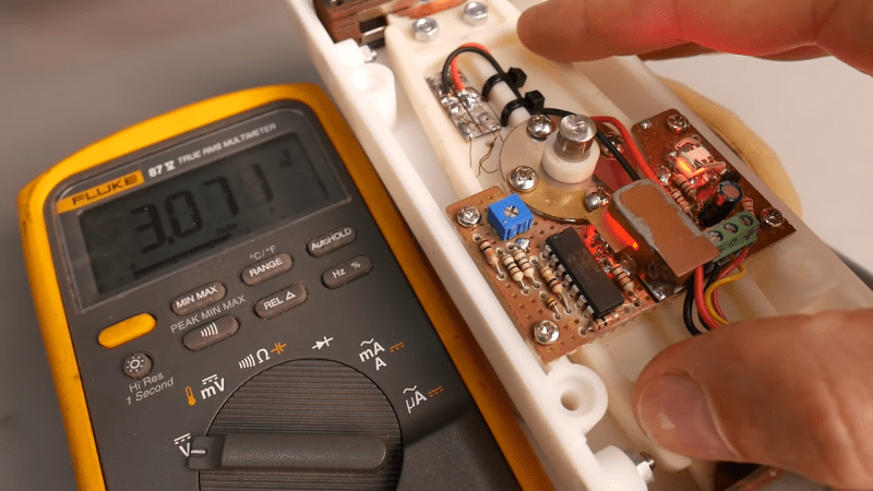
[Leo]’s torque transducer is completely DIY, consisting of hand-wound coils on the ends of a long lever arm that’s attached to the output shaft of the engine under test by a magnetic coupling. The coils are free to move within a strong magnetic field, with a PID loop controlling the current in the coils. Feedback on the arm’s position is provided by an optical sensor, also DIY, making the current necessary to keep the arm stationary proportional to the input torque. The video goes into great detail and has a lot of design and build tips.
We just love the whole vibe of this build. There may have been simpler or quicker ways to go about it, but [Leo] got this done with what he had on hand for a fraction of what buying in off-the-shelf parts would have cost. And the whole thing was a great learning experience, both for him and for us. It sort of reminds us of a dyno that [Jeremy Fielding] built a while back, albeit on a much different scale.


It’s a “Stirling” engine. And typically also a “dynamometer”
Fixy-fixed. Thanks.
Tag: teansducer
if you are going to use fancy pants Latin phrases, at least spell them rite.
Fixed it, thanks.
And you might want to think about spelling the very subject of the article correctly as well. Stirling, not Sterling. Come on!
Isn’t “Dynanometer” supposed to be Dynamometer??? :)
Blergh. I initially had that in my first comment as well, but the comments screwed up ;-) Thanks for pointing that out as well.
Maybe Dan is learning from Reddit ;-). “How to increase engagement on your posts by intentionally mis-spelling a word so that people rush in to comment on the mistake and upvote the post to increase visibility of their correction”.
“Dynanometer”, “Sterling” engine, maybe HaD ought have a proofreader?
Dan, that was a very gracious reply. Hats off to you.
He who writes about stirling engines, may get piston.
Piston and told it’s raining.
Sterling example of Stirling engineering.
Pedantic comments aside, the project really *is* a sterling example of homebrewing. Completely awesome explanation and detail of the mechanisms.
More like this, please!
Agreed – there were so many intriguing techniques and approaches to fabrication in that video. Thanks for posting, HaD.
Want a really easy and darned linear programmable load (brake) for a dynamometer? Use a DC motor as a load, driven by a constant-current supply.
The motor (load) torque is linear with current, irrespective of speed. (within reason: there’s still bearing friction)
From the voltage generated you can also get speed too, but needs to be adjusted for IR drop in the motor resistance to be accurate.
And Dan: noli illegitimi carborundum
“DC” motor tends to mean a BLDC motor these days so there’s a caveat in finding one of suitable size.
Interesting that one would conflate the two terms. I had no idea there was any confusion. Though I hope that a HaD reader bright enough to employ this technique would know the difference.
Just for giggles, though, I looked: The first page of results on Amazon for “DC motor” returns dozens of brushed motors and exactly one BLDC. Likewise Aliexpress: only two of the dozens of hits are BLDC.
Traditional DC motors these days come in toy motor sizes. Anything larger – something you could use for a magnetic brake – tends to be BLDC instead because efficiency starts to matter.
Like you, I did an Amazon search, and it gave me a whole bunch of 3-6 Volt mini motors.
Messing about in the CNC retrofit game we see multi-kilowatt DC motors. Though to avoid ambiguity the phrase normally used is “brushed-DC”
One thing I didn’t like about the position sensor is the assumption that the two LED pairs are going to behave the same in regards to temperature and output.
It’s assuming that since this LED is doing this, then that LED must be doing that, which is not a given. Instead, he should have put two sensors on the same output LED – one to measure the brightness, and another to measure the overlap.
That is still assuming that the sensor output is temperature-independent and does not change in the same direction with the sensed effect. For LEDs the Vth commonly drops about 2 mV/C so the measured brightness seems to be dropping as it heats up. The temperature compensation is liable to over-compensate the current beyond what’s necessary to maintain constant brightness, with the danger that could run up to overheat the diode if it can’t find a thermal equilibrium. In any case, the circuit doesn’t seem to be doing its job and the whole thing is an example of “cargo cult” engineering – you think it’s doing a job because the logic is there, but actually the difference it makes is so tiny that you can’t really tell whether it’s working at all. As the guy said: you should do the sketchy thing first and see whether no compensation at all will perform well enough, before you put in the time to make elaborate schemes to get it down to the last decimal point.
Thankfully, it is not even important here where the actual center is, because he’s measuring the current required to counter the torque and keep the beam steady. This current will be virtually the same whether the beam is angled 0.1 degrees more one way or the other, and the beam will necessarily do so anyways because his PID can never get the error voltage perfectly to zero – you need to give it some slack, or it will turn into a vibrator – so the temperature compensation for the center drift was not necessary and he could have left it out.
Ultimately, if you want to get rid of the whole temperature problem, the sensor should be constructed out of two LEDs side-by-side with a diffuser on top, so you can measure the difference between them – not the absolute brightness.
That way, as long as the LEDs are reasonably similar, the common mode error is eliminated. The center point will remain the same regardless of whether the light sensitivity of the LEDs changes, or the brightness of the source changes. What does change however is the sensor output gain, so the amount of millivolts per millimeter of deviation difference you get can vary with temperature and time, but this has the same effect as slightly changing your overall PID gain – which for the purpose of the job isn’t all that critical unless you’re relying solely on the P term.
No, you have still not “fixed it” with your spelling.
The narrative of your article still contains the wrong spelling of “Sterling”
(at 09:04 7 Apr 21 GMT)
Damn, I thought this was about beer.