Op amps are generally pretty easy to apply, but there are some practical nonideal behaviors you have to keep in mind. [EEforEveryone] takes a test board with some 2X amplifiers on it and — after some fiddling around with the scope probes — demonstrates the effect of capacitive loading on the output of an op amp. (Video, embedded below.)
The op amp in question is the OP07. In fact, there are two identical opamps looking at the single input. The output of one op amp feeds directly to the scope probes. The second one passes through a bipolar transistor buffer consisting of an NPN and PNP transistor. Both outputs have optional capacitors that can be jumpered in or out of the circuit.
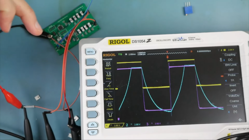
With no capacitance, everything works as you’d expect. The signal goes in and both outputs produce a perfect replica at twice the amplitude. Adding capacitive loading distorts the output signal and, as you might expect, the more capacitance on the output, the worse the distortion. The buffer does help, but there is still distortion.
The narrator mentions he probably should have used a worse op amp to accentuate the problems with trying to drive high capacitive loads, including instability. But even with the high-performance op amp, you can see that adding the buffer is definitely desirable. There’s no free lunch, though, as you do lose some output voltage range with the buffer in place. In the end, you can see an example of trimming the op amp, as well.
If you prefer to do your experiments virtually, you can do that. If you do, don’t forget to try all the simulations.


It seems the video just shows low-pass behavior due to the output impedance. With some opamps, it becomes much more unstable with even a small capacitive load: https://jpa.kapsi.fi/stuff/pix/stable.png (unfortunately I can’t remember exact setup for the image shown).
Yeah. Instability usually means unintended oscillation or ringing…
It’s hard to find an op-amp bad enough to have stability problems these days, you might have to find a makerspace with a stockpile of really old parts that nobody ever uses.
741 on an import, low-quality breadboard with no decoupling caps.. make sure you have a 21″ trinitron close too (preferably on).. also helps if you are in a room full of fluorescent lamps with electronic ballasts..
I wish that were the case. You are on a site where people insists on using parts from the1970’s like DIP, 5V TTL, 7805, LM358…
Ironically the 7800 series is excellent for low noise since it doesn’t act funky with additional capacitance but rather only gets better.
Can’t say the same about some more modern LDO’s, they like to oscillate if it isn’t just right.
Though it acts like a programmable resistor with a fixed minimum voltage drop and output voltage, so efficiency isn’t something it likes to talk about.
So it’s more that you shouldn’t use something like TIP120’s when there’s parts available that’s both better, just as available and just as cheap or cheaper in the same package style.
But if you wanna use them as part of a programmable load/heater, I guess their disadvantage suddenly is a advantage.
That reminds me of people who build discrete audio amplifiers and are surprised when these start to oscillate at the RF range. That’s what one gets when each and every transistor has bandwidth of 30 to 300MHz…
You can’t just group modern LDO into the same thing. Some are designed for low quiescent power, some are for being cheap, some are for RF and some older parts aren’t even low drop. The latter (pre ceramic bulk cap era) tends to oscillate with large ceramic caps just like your average 1970’s 78xx do.
The 7800 part isn’t all that great compared to some of the new LDO parts designed for noise sensitive RF application and post regulation after switch mode supplies. The Ripple Reject curve of the 78xx drops off over frequency. A LDO with higher bandwidth extends that curve into higher frequencies. Once over the frenquency, external caps does most of the work. The 78xx series is unstable (i.e. oscillates) with large values ceramic caps and this is when that make it not a great part. New LDOs designed after ceramic bulk caps becomes mainstream can handle bulk ceramic caps.
The reason why I initially comment is that LM358 is probably the worse generic opamp any “makers” could use. The are flooding the usual “makers” channels because of profit. It is not forgiving nor good in any sense – cannot handle even a reasonably capacitor load, limited common mode input range and poor output impedance and output ranges. It is really a part for engineers that know all its short coming, but still choose to use it because it is cheap. Makers are too lazy to even read the datasheets, so they should really use a more modern and better part like @RubyPanther mentioned.
I like the LM358 because it will tolerate greater than supply voltage on its inputs. So you can use it to buffer big inputs, and it will just clip its output to slightly less than Vin.
LM358s are cheap and ubiquitous… But if the community has better suggestions, I am all ears :-)
BTW be ware of parasitic capacitance as some of them can exceed the capacitance load for stability. e.g. MOSFET gate capacitance, long coax cables…
You should be able to go rail to rail using a diamond buffer. Especially if it’s bootstrapped.
This capacitance thing he’s running into is from the op-amps’ native output impedance. The poor transistors on the chip going, “I hope I can”. Low Ζ headphones can cause this too.
Ever use an “uncompensated op amp” like Fairchild’s original uA709? Those early parts were super temperamental. Then along came the reliable (albeit now ancient) uA741, one of the first unity gain stable parts on the market. That was a big milestone and no longer required a PhD to tame an out-of-control op amp. Capacitive loads have long been a bane to op amps because they can cause feedback into the input sections, even due to poor supply rejection (that’s why we need the bypasses!). Like any endeavor, you have to learn to navigate through the rough spots, but once you do, it smooth sailing.
There have been lots of improvements to op amp tech over the years, with JFET, superbeta inputs, MOSFET, etc. inputs, single supply operation, rail-to-rail outputs (and inputs!). All in all, their basic designs haven’t changed much, but their underlying construction has gotten much higher in gain-bandwidth. Some op amps can even still reverse output polarity if their input differential range is exceeded. When I was the “young engineer” I had trouble convincing the “experienced engineer” that the problem with is RF amp was maybe related to polarity inversion on the phase control op amps. We had problems with his original design for over two years before he came over to me and admitted that I was right. It’s not hard to test, but it’s hard to convince someone that doesn’t bother to listen and test (besides, IT WAS IN THE MANUFACTURER’S DATA SHEET!). For some, these are obstacles in their path, to others, they’re challenges to be overcome.
As a diy music enthusiast I can say a word about these boards and ICs. Any music fx became famous because of bad and malfunctioning boards, ran behind normal specs and mostly because of cheap components used in build. I think it will be interesting to run some sound signal to see how it affects the sound.