There is a gotcha lurking in wait for hackers who look at a piece of equipment, see a port labeled “Serial / RS-232”, and start to get ideas. The issue is the fact that the older the equipment, the more likely it is to be a bit old-fashioned about how it expects to speak RS-232. Vintage electronics may expect the serial data to be at bipolar voltage levels that are higher than what the typical microcontroller is used to slinging, and that was the situation [g3gg0] faced with some vintage benchtop equipment. Rather than deal with cables and wired adapters, [g3gg0] decided to design a wireless adapter with WiFi and Bluetooth on one end, and true RS-232 on the other.
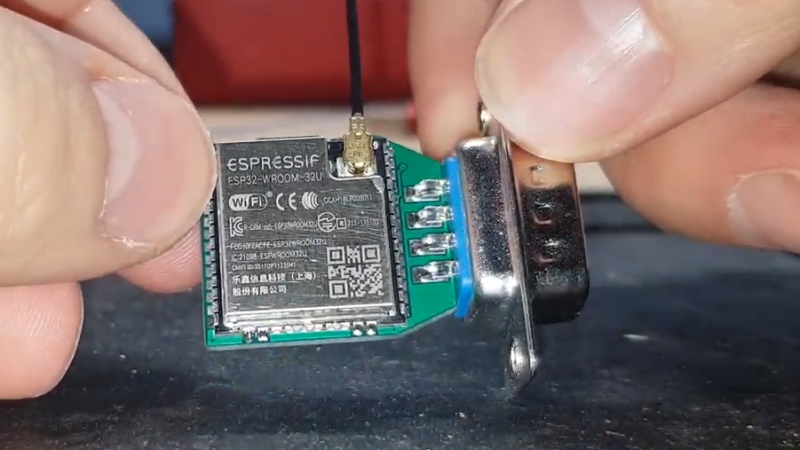
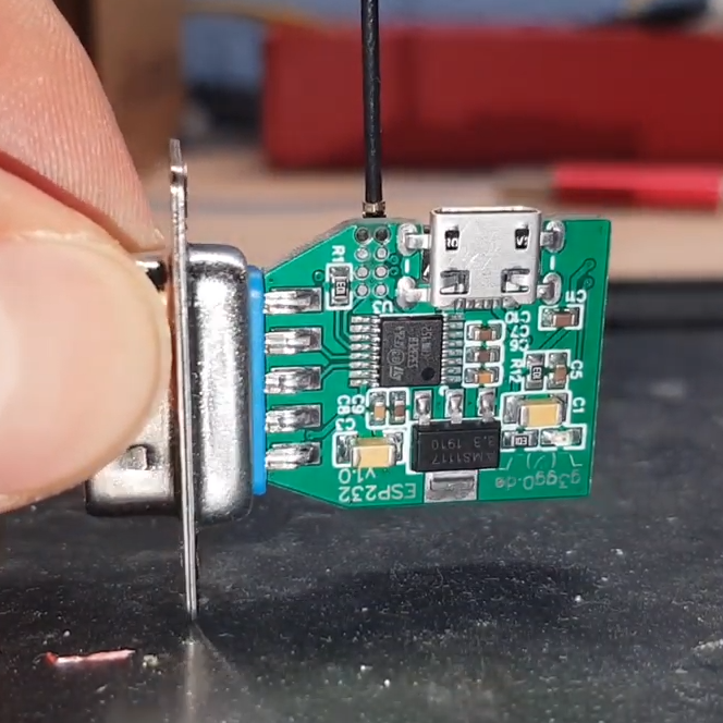 The adapter features an ESP32 and is attached to a DB-9 plug, so it’s nice and small. It uses the ST3232 chip to communicate at 3 V logic levels on the microcontroller side, supports bipolar logic up to +/-13 V on the vintage hardware side, and a rudimentary web interface allows setting hardware parameters like baud rate. The nice thing about the ST3232 transceiver is that it is not only small, but can work from a 3 V supply with only four 0.1 uF capacitors needed for the internal charge pumps.
As for actually using the adapter, [g3gg0] says that the adapter’s serial port is exposed over TCP on port 23 (Telnet) which is supported by some programs and hardware. Alternately, one can connect an ESP32 to one’s computer over USB, and run firmware that bridges any serial data directly to the adapter on the other end.
Design files including schematic, bill of materials, and PCB design are shared online, and you can see a brief tour of the adapter in the video, embedded below.
RS-232 on serial interfaces was around for a long time, so we’ve definitely not seen the end of projects like this. [g3gg0]’s board would sure have made it easier to IoT-ify this old LED signboard.


*DE-9 not DB-9
D-subminiature 9 pin connector size E.
https://en.m.wikipedia.org/wiki/D-subminiature
Wow, someone beat me to it!
What I’m really struggling for at the moment is to connect an RS-232 only console device to a device which only has USB console.
Several new models of enterprise UPS now come only with USB console, meaning we can’t connect it to our console servers.
We have ethernet access to them of course, but always good to have console there as a backup.
I’m wondering if one of these could be setup to connect to the UPS USB console, and pass that /dev/ttyUSBX interface out to a onboard DB-9 / DE-9 – or better – an RJ45 cisco/YOST port.
Sorry – inadvertently replied when I meant to post a new message.
Are you trying to remote boot the server? or querying the UPS for event status? Most of the large servers I have worked with have alternate NIC adapters that allow direct rebooting/control via console of the server through that separate internet connection. Which can save you if a reboot doesn’t take after an update and the server is 500 miles away in a secure facility at night. So electrically “pulling the plug” if you will, but for the server, not the UPS.
They do have inexpensive USB to RS232 adapters for like 12 bucks, a USB cable with a RS232 head that has the circuitry in it. The big problem I always found was that writing software with those devices can be hard to interface via USB if you are rolling something say in DOS that needs a special USB driver (since comm 1-4 was only available before USB without special boards) – given the USB cable installs comm as like COM32, etc. It shouldn’t be effected with terminal software, all of which I have seen address the issue and allow USBCOM with a very large range.
I struggled with that, too. And then I made a DE-9M to USB cable using cheap-o “cisco console” cable and a blank DE-9M to RJ45-female part from Startech.
Details here: https://wejn.org/2021/02/howto-usb-cable-for-APC-Smart-UPS-SC450RMI1U/
Maybe it can help?
I mean, this solution is for sure sexier. :-)
Thanks – unfortunately that does the opposite of what I need
It’s not esp32 but a raspberryPi based solution that should provide what you’re looking for.
https://github.com/Pack3tL0ss/ConsolePi
True. ‘B’ is a 25 pin while ‘E’ is 9.
I’ve never heard of the “DE-9” connector. They are used interchangeably apparently. I always thought it was DB-9. “B” being the shell size – Weird. It’s also very possible that I have brain damage. I think it’s the miles, when I hit 60 stuff started failing….especially my brain. I know this because development projects that I created were done by someone WAY smarter than I am looking back now on the code. :)
Just keep calling it a DB9. We nerds can be pedantic. I’m also too old to really care about trivia like this.
+1
I find that “Dsub ” works well, e.g Dsub 9, Dsub 25 etc. Technically more correct than saying “DB” for everything, but you don’t actually need to know any of the correct letters for each port.
They were always DB-9s when I connected them to the circuits I was designing, but now we’re talking about old guys designing “vintage” circuits. Sigh… Yeah, 60 does cause brain damage… Damn.
I thought so….They should warn us before that happens. What were we talking about again? :)
I don’t know, vintage wine?
So we been calling them the wrong thing for over 2 decades?
Almost 4 decades for me, and apparently. The only good thing about it is I know if I go another few years I won’t remember anyways….
Won’t remember what?
4 decades from my experience. :)
I’d like to see such a simple.tiny adapter but for ethernet (to wifi) instead.
So basically a router, but tiny?
I’m prety sure the esp32 has an ethernet MAC, so should be prety simple on the hardware side. In fact, this might have been done by somebody on the internet.
you can (could ?) already buy them. i have used a handfull of them. you are looking for a “wifi ethernet bridge”. there are a few solutions. i used to use the NETGEAR WNCE2001 Ethernet to Wireless Universal Adapter. it needs power, you connect it to the wifi over WPS (i think it also had a basic web interface) and it has one ethernet port and will brige between them. you could connect any device with an ethernet port to the wifi with this adapter. but i guess it is not as uesefull these days anymore. most devices have wifi build in nowadays.
But it’s *gigantic* in size.
it’s over 10 years old and also EOL. it was just an example that this kind of device already exists for quite some time. someone has posted smaller devices below.
you mean this?
https://de.aliexpress.com/item/4000366124345.html
That’s the first device of its kind that is actually compact. Is it powered parasitically or does it need external 5V PSU ?
The schematic shows a micro usb-B connector with 5v needed. It uses an AMS1117-3.3 regulator to reduce the operating voltage to 3.3 for the chip if I’m reading this correctly.
Thats true for my ESP232 adapter. I think Nath referred to the aliexpress part that i linked.
He was in search of an Ethernet/Wifi Adapter that small.
That aliexpress thingie does not have any connector from the looks – you have to provide 5V there too.
Looking at the schematic, it seems like this really isn’t true full RS232, it doesn’t have any hardware handshake protocols, only software handshake presumably – DTR is wired high all the time, which without a ring buffer/16 byte FIFO on a typical UART runs the risk of overrun, and since this will be connected to some old funky hardware – it’s unlikely that hardware will have overrun protection on it’s chips. Given I can’t see the code, even if you implement a ring buffer there you still can’t know if the device can receive a character unless it supports Xon/Xoff, and I can tell from experience a lot of hardware didn’t.
Maybe I’m just being too critical. But figuring out how to pass RTS/CTS signals back and forth to the connectors would solve this issue I believe.
No one has heard of Lantronix ? These same things have been there for over 10 years.
Ethernet to serial bridge or Wi-Fi to serial bridge.
https://www.lantronix.com/products-class/wired-device-servers/
Or Comtrol.
https://comtrol.com/products/devicemaster-ethernet-device-servers
hmmm, how do I make that link??
The Lantronix UDS-1100 and the 500-171-R adapter was such a wonderful thing for RS-485 work, astonishingly wide power input capability and astonishingly capable RS-485 just doonk doonk doonk right there. Sturdy units too! Had a failure mode once where the accumulated ice ripped the RS-485 wires in half… but the device server kept running!
USB is only used for power(D+,D- are unconnected)
Yeah, correct.
My text only meant that you could use a *second* ESP32 board and use it as a USB/WiFi/RS232 bridge.
Maybe a bit misleading in wording, will clarify this.
+1 for the ESP232 name :)
“a bit old-fashioned about how it expects to speak RS-232”
How can you be old fashioned about adhering to a standard? This standard doesn’t say anything about the data format as you imply, it does say a lot about the physical and electrical characteristics.
Asynchronous serial data using 0/3v3 or 0/5v has nothing whatsoever to do with RS232, beyond being capable of being converted to comply.
Yeap, -12 to +12. It was always a pain to need to build dual power supplies for projects that used RS232. The Maxim chip made a big difference on that when it came out.
The MAX232 was/is a bit limited, though. Only three or so data lines could be handled simultaneously, if memory serves. :(
Anyway, the charge pumps (right English term?) were really useful. The MAX232 could be used as a generator for +/-12v, I believe.
Right term “charge pumps”. It was that dual +/- supply that made it so attractive for projects. Of course you could always make a simple power tap with a few diodes off an existing step down transformer. And most TTL circuits were 5 volts since CMOS wasn’t widely used until the 80’s anyways – you were stuck trying for a dual power supply +5/ -12+12 . Although the +12/-12 supply was very low current and didn’t need anything beefy.
But in a day when even transformers for 1 or 2 amps at 15v were like 20+ dollars at Radio Shack a hobbyist had to be careful what they used. The wall warts didn’t seem to be widely used at that time as an alternative – I think it was because they couldn’t provide enough current for any major device without becoming a large component in itself. The old ones I have (used on some modems – 300 baud speed demons) are like 3″x4″x3″ just for a 5v/2 amp output.
He offers the Schematics and Gerber files for the PCB but not the firmware….
it’s nothing special, just a small arduino project with optional OTA enabled.
the only special thing is the “enable OTA” mode when you bridge Rx/Tx.
(had problems with OTA causing spurious resets within WiFiUDP code, thus i disabled it by default)
will upload it the next days, stay tuned.
pushed the source:
https://github.com/g3gg0/ESP232
I tried to get the arduino code running, but did not manage to do so (yes, I am a newbee using arduino but not in embedded/C/C++). I assume the code is not complete. As an example, WebServer.h cannot be resolved (but is referenced). Which IDE/environment did you use?
There are multiple references to webserver.h on Github and in the Manage Library section of the IDE. I’m not sure which one you need, but it seems to me that certain libraries for a given arduino have it – maybe snatch one. Check your board in manage library section and see if the library is available for Webserver. Anyways here is an example: https://github.com/espressif/arduino-esp32/blob/master/libraries/WebServer/src/WebServer.h
Thanks, BobbyMac99 (- why didn’t I find a reply button below your post?)
Of course, you are right: I have to include/link the right library. But that is the point: which of the tons of existing libraries is the right one? Also, the esp232 code was intended to work with both, esp32 and esp8266 (and I currently play with the latter). For anybody not at home with arduino this is a nightmare.
Not sure on the reply button. And yes, I agree – sometimes it is difficult to figure out which one to use. I start at the module required if searching online and then check availability for board. There is always the possibility that if you have some new variant board that a library won’t be available for it yet. But in the Library Manager in the IDE, the board usually shows up in the list for compatible boards in the actual library listing.
So WifiWebServer would be listed, having the board in the usable list right next to it’s description. I usually do a search in the library manager search box at the top of the listings if going that way, although just searching online usually shows it too if not in the IDE, then you can download it, add it to your existing libraries.
In the end, knowing if it will work comes down to the exports in the .h header file. So if the author of the project doesn’t specify which module, try the IDE one first and move from there. Also, many times you need just a single value or so from the.h file, like a coded buffer size instead of actual code export, I tend to look at the compile errors and see if those equates are contained in similar other packages with the same board that has similar memory characteristics if you are really stuck – and research the error if the module is not available (I suspect not likely if it is a comm module though). Given the number of boards supported these days I’m not sure this occurs very often
I think I did (tried) what you suggested. Probably I was mislead by some code lines (such as #if defined(ESP8266) …) to assume that the code would be working also for esp8266. In fact it seems to be not: some libraries (e.g. freertos/queue contained in ESP8266_RTOS_SDK) are not available – at least the framework is not applicable to a wemos D1. Ok, I need to organize a true esp32 to be more successful …
woah great stuff thks for sharing it, will order some boards
RS-232 is a 25 pin physical standard. Is this EIA/TIA 574?
Many manufacturers went to db9 connectors for terminals. Only the DCE stuff really used a full 25 pin connector since they were expensive back then and not really needed for terminals. So DTE would only use send, receive, signal ground, and DTR, maybe RTS/CTS. But most video terminals could handle 19200 baud without overrun so they didn’t bother with handshake other than Xon/Xoff and DTR for terminal ready. (Data Communications Equipment, Data Terminal Equipment)
Since I used to teach serial communications, I understand all the leads, which is why I know that a 9 pin interface cannot be RS-232, thus my question, is it 574?
RS232 is an electrical standard AND a protocol – sort of. While most People commonly see it as a connector style, it really isn’t. Originally RS232 used the DB-25 connector. The DE-9 (As I have been corrected) RS232 interface uses RS232 signal levels. They just crunched down the number of pins that were used into a smaller connectors when IBM went to the PC standard serial ports, other manufacturers, like Contel also used 9 pin connectors for their terminals, mimicking the pin positions as close as possible and the signal levels. Those MAY match 574, depends on who made the interface.
There were a lot of different companies doing their own thing when it came to comms. It’s why RS232 was such a wild west area for a long time – you needed a breakout box on some systems to figure out the pin assignments, since many used the 8250 UART chip, others, not so much. On Contel systems we had to make custom cables for a given device, even though they followed the signal levels correctly. Another example is Honeywell Level 6 systems, they used RS232 levels, but inverse signals for things like RST/DTS from the standard.
We think of DTE as pin 2,3,7 and 20 normally for RS232/DB-25. Obviously DCE commonly used for modems required the larger connector because it used more signals like RTS/CTS and may others. Since 574 is listed as a separate standard from RS232 I would say no, but I can’t speak to the electrical characteristic of that standard when compared. But that doesn’t mean they aren’t overlapping.
Here is a datasheet with multiple standards listed individually with the pin outs, maybe that better explains the standards: https://www.ti.com/lit/an/snla039/snla039.pdf?ts=1618889377562&ref_url=https%253A%252F%252Fduckduckgo.com%252F
If anyone is interested, I’m pretty sure this leads to putting a full wireless terminal on it with VGA output, it has multi-language keyboard and on board setup features, making it really easy to use. This is one I have built many times, which you can get the software for – VT100 emulator (Geoff’s Projects): https://geoffg.net/terminal.html
Oh, it also does composite video out, and it was covered on Hackaday: https://hackaday.io/project/173216-ascii-video-terminal
The standard allowed a range from 15V to 5V, positive and negative as I recall – I still have a couple of the Maxim chips in my component drawers, they used +10 and -10 and worked with everything I ever tried them with.
Rats! I replied to the wrong comment… oh well, BobbyMac, you know which comment I was replying to ;~P
Yes. But I remember distinctly that +5/-5 wouldn’t work on may printers and terminals. They needed a higher swing/crossing voltage. It’s possible that it was 15v, I just always used +12/-12 since that was what the equipment I was working on used. Not sure I have ever used the maxim chip other than the terminal hardware I posted on. I just always used the spec I had been accustomed to. I still have 25 pin and 9 pin breakout connectors and cables for that stuff, even null modem cables – just can’t bring myself to throw them away. Interesting thing though, when People talk about “RS232 Standard” it never really was, I mean on paper – but if was pretty much the wild west in the 70’s and 80’s for RS232 and the pin outs. Remember 20ma current loop? Man that goes back a long way.
RS-232 standards, pick one or make up your own. Quite some time ago, it was a running joke.
I love standards. So many to choose from.
You could combine an ESP8266 HC22 4 pins to the 4 pins of an RS232 MAX3232 TTL adaptor:
http://zoobab.com/esp8266-hc22
https://www.aliexpress.com/item/4000055222836.html
And install the jeelabs firmware to do the serial bridge:
https://github.com/jeelabs/esp-link
A glimmer of hope for Ethernet-free CNC-machines e.g. from fanuc :)
I don’t work with ‘server’ servers – I’m a network engineer primarily :)
I’m referring to console servers, like Lantronix, Perle, Comtrol etc.
All ours are Serial only, and changing them out isn’t feasible (we’re talking thousands of them) Sadly these new UPSs only have usb console, no RS232 console, so I’m wondering whether we can hack together a microcontroller to convert from USB to Serial – but in the opposite direction to the way most people do.
LOL – I try to leave a root level comment and it replies to a random other comment, then I reply to a specific comment and it turns up as a root comment.
Or this? It needs to be DCE (both directions), this is a null modem cable that should work I think: https://www.amazon.com/USB-Serial-Adapter-Modem-9-pin/dp/B008634VJY/ref=sr_1_11?dchild=1&keywords=usb+to+rs232+cable+bidirectional+DCE&qid=1618853344&sr=8-11
Will something like this work? It should be bi-directional: https://www.amazon.com/EZSync-Programming-Controls-Sinumerik-EZSync014C/dp/B077TVBF54/ref=sr_1_18?dchild=1&keywords=usb+to+rs232+cable&qid=1618852833&sr=8-18
Unfortunately no – both of those are for connecting an RS232 device to a USB host.
What I need is the opposite – to connect a USB client to an RS232 host.
That is going to require an active device like a microcontroller or SBC that can connect to the USB device, get the virtual serialport (usually /dev/ttyUSBx or /dev/ttyACMx) and then connect that to an onboard DB9 that my console servers can interact with.
I’ll probably give it a go with an RPi to prototype, but was wondering whether the microcontroller here would do it.
Thanks all for the responses!
CH559 has USB host, would be fun to do the reverse USB->TTL.
Interesting, I’ll take a look, thanks.
So a lot of micros have USB host capability (acting like the computer, not the peripheral) though I’m not sure I’ve seen any examples using cdc-acm USB serial. If your devices use some other proprietary USB serial adapter, you’d be even more on your own. (I assume you have fancy enough ups that they don’t use the HID UPS protocol like my consumer one? That would actually be easiest because hid is probably the most popular thing to host on USB on a micro. Cdc-acm always seems to be crazy complex, at least in the descriptors.)
Ah I remember the days of the Apple //e, 7 modems, and a little piece of software
called Diversi-Dial. The modems were internal and took up the 7 slots in a //e.
300 baud chat with a rudimentary email system, quite advanced for the time.
I met my first love on such a system. I find it heartening that people still
use RS232. Today, with our gigabit ethernet and multi-meg download speeds,
that 300 baud seems ancient by comparison. Still, it’s nice to see people
remembering the past, even if it is wirelss RS232.
This is incredible nice and useful. If someone made this in a case for a reasonable price I would def be in the market instead of adding a RS232-TTL converter that is as big as the MCU.
Isn’t this literally the reason why the ESP8266 exists, but it was “hacked” to become more in the form you know it today? Its still sold as a WiFi Serial adaptor
That’s ttl-level serial (well, lower actually, since I think technically ttl is 5v?): 0v to 3.3v. “RS232 serial” (desktop serial port serial) is the same basic protocol (as most often used – though it frequently has some extra control lines), but with a huge voltage swing, like -12 to +12V. That’s why there’s the extra chip on the back of the board – to convert the signal voltage levels.
Back in the day rs232 meant more, I think, with all kinds of flow control, etc lines, but at least as far as I hear it uses, it mostly means tx, rx, maybe cts/rts/dtr, and a big bipolar voltage swing.
Yes. The ESP8266 was originally brought to market as a wi-fi to serial bridge, and someone figured out how to stuff their own firmware on it. Esprif didn’t miss a beat and embraced people putting their own code on it and released an SDK. Funny how sometimes when things go full circle, people don’t realize that they’re back where they started.
The 8266 can be programmed in Lua. Simple to learn. Biggest problem is the loader doesn’t strip comments, so you need a sed script to strip the comments. The internal storage space is limited, but enough for a reasonable application. You can define a simple html web page.
Do you take orders?
Another, only slightly less old guy here. Your memory is correct. DE-9 is actually OLDER than you are familiar with. The internet has a way of turning some things upside down. Way back in the day when Cannon made the D-sub family, they classified the sizes as A through E. Most electrical supply houses ditched that and just called them all DB connectors. Even today, particularly if you are ordering cables, DB9 is a better search term. I ever saw a DE-9 package at Radio Shack or the local electrical supply houses.
Here is one example: https://edac.net/products/db9-connector/145 which actually mentions DB9 as the current term and DE-9 as the old term.
So while DE-9 is technically correct, some supply places don’t show up on searches for connectors if you limit your search to that term and your brain is ok, at least this part of it!
Ah RS-232. I remember when we had to have all 25 pins connected to get some DTE working (they used the secondary channel for control information). DB-9 stuff wouldn’t have worked!
I am looking for a BlueTooth or infrared solution replacing a USB to RJ12 serial cable for connecting a laptop to a amplifier. I only need RX/TX/GND. Any ideas?
Hello, are sch/PCB files still available?
Good question, OSCWlab looks like the link is broken from the original post. However, if you search there it does turn up some more recent projects since the original thread here, maybe more useful: https://oshwlab.com/search?wd=esp32-rs232
Yes, I noticed that.
There is some new projects, but none really compact like this one. It would be great if someone has saved files of this PCB. 😁