As amazing as CircuitPython is, it hasn’t yet been ported to any 8-bit microcontrollers. [Chris Heo] was unsatisfied with his inability to use Python on his 8-bit ATmega4808 AVR, so he worked out a way to zombify it and bend it to his will using Python on his PC.
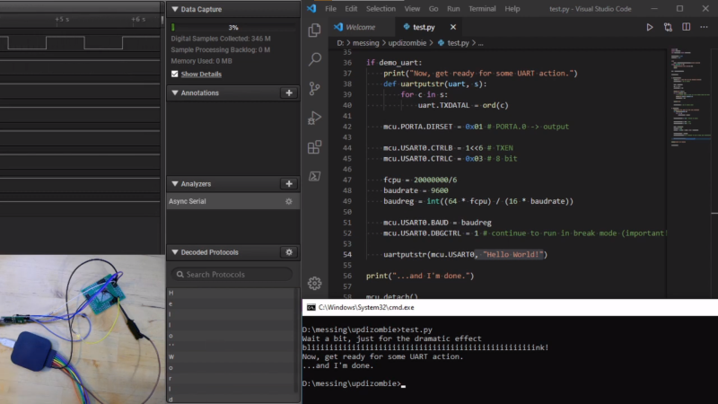
The trick to making this all work is the UPDI interface: a single-wire UART interface for programming and debugging Microchip’s newer 8-bit AVR microcontrollers. UPDI reaches deep into the microcontroller’s core, allowing you to stop and start execution of microcontroller code and access all of the onboard data and I/O. [Chris] realized this could be used to stop execution of any code running on the AVR and directly control the output pins using the pyupdi library. Since UPDI lets him modify the AVR’s I/O registers, he was also able to blink an LED and use the microcontrollers UART to send a message back to his PC without compiling a single line of code.
This may seem like an entirely unnecessary hack, but for devices too small or basic to have a JTAG interface for debugging this could be the best way to test and debug peripherals in an assembled circuit. We hope this catches on and would love to see how much of the chip can be controlled in this way. Maybe this will make it easy to experiment with the programmable logic that’s on some of the newer AVRs.


Good stuff. I have a general question that I would like to get other peoples opinion on. When doing register manipulation like in the above screenshot, what is your preferred way of setting the initial bits? I find that when im using the 8 bit MCUs I stick with something simpler like: TCA0.SINGLE.INTCTRL = 0b00010000 instead of something similar to TCA0.SINGLE.INTCTRL = 16 (or its hex equivalent). I find it makes debugging easier when developing along with the datasheet but I often see so many other ways of doing it that I think maybe I should change it up a bit. What approach do you take?
I’m a newbie to register manipulations, so I do that as well, with a brief comment above saying which bit does what if it is something I manipulate often. Like you said, it makes debugging easier. The only exception would be when only one value ever gets written to a register (e.g. lock keys), because those never change.
I’d use copious defined so that there were fewer numbers appearing in the code.
And I’d use a shift to make it clearer (to me atleast)
TCA0.SINGLE.INTCTRL = 1 << 5
For 8-bit AVR microcontrollers all configuration registers are accompanied by sets of defines for the individual bits.
So I initialize the registers that way :
TCCR0A = 2<<COM0A0 | // Non inverting PWM
2<<COM0B0 | // Non inverting PWM
3<<WGM00; // Fast PWM mode
Here the bits are in pairs, COM0A0 & COM0A1, etc. So I "combined" them and used a decimal value to setup that pair.
An other simpler example with single bits :
TCCR0B = 0<<FOC0A | 0<<FOC0B |
0< Fast PWM, TOP = 255
1< 43.2 kHz
Well, the second example was supposed to be simpler but the in-line comments got messed-up. Here it is in one line without comments:
TCCR0B = 0<<FOC0A | 0<<FOC0B | 0<<WGM02 | 1<<CS00;
Don’t forget, CircuitPython is a derivative of MicroPython.
While there isn’t Python for AVR per se, there is Snek, which is very very close to Python for all practical purposes: https://github.com/keith-packard/snek
is it possible to write direct in the cpu-pipeline w/o flash-interaction with UPDI?
Why bother with the AVR CPU core when you already have full access of all the I/O registers (and memory space) already. The python script is the CPU. It is more like puppetry.
Exactly!
Also I guess having the full control over the core won’t be possible as you AFAIK can’t execute core commands via UPDI. If I didn’t get it wrong this would be possible if you could execute code from RAM (which the AVR architectures don’t support).
So you would write the code to the RAM and change the program counter to that location and hit run.
This way the could get rid of the speed penalty from the UPDI interface but it would be a completely different approach from what I wanted to reach.
Another thing I started (bot not yet continued) to look into was retrieving RAM images during runtime of “real” code and map it to global variables. This could be beneficial for automated testing, especially when automating it via breakpoints. Unfortunately the project where this could be used died, but it might get interesting again ;)
It is one thing to have Harvard architecture behind the hardware, but it is a pain for the user if that becomes a limitation of what the user can do. I have seen 8051 projects that uses a unified program and data space with a simple AND gate in the address decoder.
I like the STM8 series as it has taken memory mapped I/O like Arm. You can run code in RAM or even in EEPROM. They have fully documented their SWIM hardware debugger protocol. The usual $2 STLink clones suports hardware debug with source level debugging, watch, breakpoints and let you peek/poke I/O. Sadly you have to pause the chip probably because of bandwidth and software implementation. Arm debuggers let you watch stuff live.
UPDI is a single wire debug protocol that is essetially a asnc serial port. As such, it is limited by having to sync/generate a clock(could be RC) that can vary and a large range of frequency. Having a separate clock in SWD or JTAG eliminates this problem and can run at much higher speeds. Some of them have optional sideband signals. Even then it is hard to match CPU speed and harder to get multiple bytes of info per CPU cycle.
I’ve never understood the use of python on microcontrollers for general use. Python runs slower, and as far as I know takes up more space in flash or requires external storage. For most applications C works much better and isn’t very complicated to write. For some applications you just couldn’t use python because of the performance hit you would take. In some cases I have found writing the same thing in C and Python, the python code ends up being much more complicated than it was in C.
As some might misunderstood what was done or what the intention is:
The intention was not to run Python on an AVR, also this is not an attempt to port Python to it.
Python was just the easiest to reach tool for this purpose as pyupdi is ready and working. If I had a lib in C# handy, I would have gone this way.
This hack is what it’s meant to be: creative use of a technology in the way it was not intended to. And maybe quickly (or slowly when it comes to performance) doing something on a microcontroller while having full interaction with a PC environment.
Like the following scenario in production: In-circuit testing. You got your micro and some other peripherals on a PCB you want to test. You got your BSDL for a FPGA and need to wiggle each and every pin and synchronize this in the whole system. Yes, you could write a firmware for the microcontroller and use a (not so) dedicated pin (or more) to control the test procedure.
Well, two disadvantages: you would prefer to use those pins for something else and you have to maintain another piece of software.
Instead, updizombie uses the interface that’s already reserved for programming (and will likely not be used for any other purpose) and you don’t need to write a firmware, having no trouble to synchronize it with the rest of the setup.
The way the registers are accessed is just a side effect of the features Python offers (and makes it quite comfortable to “port” code) but again, it was not intended to run “productive code” this way.
Cheers :)
“This hack is what it’s meant to be: creative use of a technology in the way it was not intended to.”
Not on Hackaday! (Gasp!) :)
Stuffing hardware in a different box (aka case modding) and artsie I-add-LED-to-this projects straightly doesn’t fall under this definition.
There is a 8051 mcu with 600MHz dual core, 1Mbytes Flash,1.25Mbytes SRAM, four channel DMA. Well, maybe that company just dont want to spend money on modern ARM core.