Arguably, the most tedious part of any Tesla coil build is winding the transformer. Getting that fine wire wound onto a suitable form, making everything neat, and making sure it’s electrically and mechanically sound can be tricky, and it’s a make-or-break proposition, both in terms of the function and the aesthetics of the final product. So this high-output printed circuit Tesla should take away some of that tedium and uncertainty.
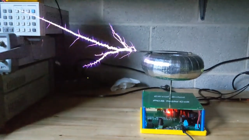
Now, PCB coils are nothing new — we’ve seen plenty of examples used for everything from motors to speakers. We’ve even seen a few PCB Tesla coils, but as [Ray Ring] points out, these have mostly been lower-output coils that fail to bring the heat, as it were. His printed coil generates some pretty serious streamers — a foot long (30 cm) in some cases. The secondary of the coil has 6-mil traces spaced 6 mils apart, for a total of 240 turns. The primary is a single 240-mil trace on the other side of the board, and the whole thing is potted in a clear, two-part epoxy resin to prevent arcing. Driven by the non-resonant half-bridge driver living on the PCB below it, the coil can really pack a punch. A complete schematic and build info can be found in the link above, while the video below shows off just what it can do.
Honestly, for the amount of work the PCB coil saves, we’re tempted to give this a try. It might not have the classic good looks of a hand-wound coil, but it certainly gets the job done.


Cool build, but I don’t think I’d test it next to a bunch of test gear like that!
I doubt this would be a problem most of the time as metal cases are/or should be grounded, which would be the same as a faraday cage in this case. Plastic cases would be a different issue but then the arc wouldn’t be drawn to that unless there was something or some place in the case the arc could go to or through, which would obviously be metal or in some cases carbon and it would likely need to be connected to a drain/ground. Still it would be prudent to not be doing this. May I suggest holding something metal in your hand while standing in water or holding a metal pipe connected to ground instead? Also notice how many times the word ‘case’ is used here. It seems to me the use of a ‘case’ around the primary part of the circuit would also be a good idea in case the HV output were to arc to that part of the circuit thereby basically cooking the Tesla circuit. In case anyone is curious as I am in this case, how many volts does one of these produce to make an arc travel this far? I have seen around 50kv go as far as 1 to 1-1/2 in. working around ignition coils for late model cars
Wouldn’t it be possible to add an audio input to make it “sing”? That would be an awesome feature !
Like in the movie ‘The Apprentice’ with N. Cage.
Yes. The H bridge should be driven by a PWM high frequency signal, whose pulse width would be modulated by the audio signal, so that the high voltage intensity would be proportional to the audio input voltage.
Interesting side note, the PCB for one of the circuit boards on starlink uses a PCB inductor design much like this.
A spark length of 30 cm from a needle source is is roughly 180KV. His driver takes 120V into a bridge rectifier, putting about 160 volts to the primary, multiplied by 240 turns makes 38400 volts at the secondary.
http://www.kronjaeger.com/hv/hv/msr/spk/
The coupling between primary/secondary is *probably* high in this configuration, assuming K = 1.0 then the Q-factor of his coil is about 4.5. In other words, the 38.4KV is multiplied by the resonance Q-factor of 4.5 to generate 180KV.
So the PCB printed secondary coil has a Q of about 4.5, which is not great. He could easily double or triple the voltage by designing a higher quality coil.
Still, it’s a neat project and throwing 1 foot sparks is impressive compared to many of the tesla coils seen online.
The problem becomes, 6mil distance between traces, for the secondary. Sure he epoxied it to increase dielectric strength, but that is more or less just a surface coating. Depending on his altitude, 10kV can jump a good distance.
https://www.youtube.com/watch?v=MIqK45nxcTo&ab_channel=StrangeParts
Surface coating does make a huge difference. 6 mil of epoxy should have dielectric strength of around 3 kV whereas 6 mil of air is just 500 V.
I wonder if these PCBs could be effectively made bifilar and then stacked with inverted polarity, so as to negate the self capacitance and increase the Q and allow a lower resonant frequency to be used.
The conductor could also be tapered because you don’t need to handle as much current as you get closer to the output, so the track separation could be increased, along with the turn count, without increasing the diameter of the pancake coil. Something tricky to do with enameled copper wire but as this is a PCB, it could be a fairly trivial thing to experiment with.
Can Tesla coils be mounted on BattleBots ?
It’s tempting to host an anything goes outdoor version and just make everyone sign a death and injury waiver.
Very cool! Next step… Make the secondary multilayer!
Also potentially useful at keeping squirrels off the bird feeder. All while making sure the coyotes & feral whatevers have enough to eat.
Just to add some interesting aspects to the discussion of voltage and arc length: keep in mind AC arcs at hundreds of KHz are quite different than DC arcs. Then toss in that they are produced by a resonant transformer, and air gap breakdown guidelines no longer fit all that well.
Quasi-continuous wave coils (QCW) are fascinating in this regard, and interesting work had been done by Steve ward, loneoceans and others. From my crude, simplistic understanding, , these coils initiate the arc then ramp up the primary bus voltage over several milliseconds. This produces thick, twisted sword-like arcs which can be as much as 10 TIMES the height of the secondary (!!). The theory goes that once the arc is initiated, each successive cycle grows the existing arc channel a bit, and many cycles as the bus energy ramps up produce the long arc. However the voltage stays reasonably low. So you get a 3 foot arc at only 80kv.
I’m planning on building one of these, just after I win the lottery (and return from island-shopping) as I will finally have enough free time on my hands :)
Forgot to add, one of those coilers observed that the resonant frequency would drop as the arc lengthened; since the existing arc is conductive it would effectively be increasing the size of the top load as it grew. I thought that was fascinating.
Also this:
https://m.youtube.com/watch?v=_fTC_Ud_k3U