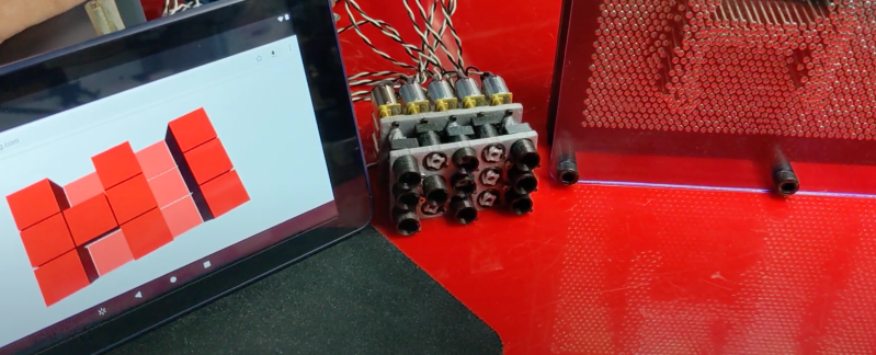
Pin art is one of those things that simply cannot be left alone if it’s within arms reach, and inevitably end up with a hand or face imprint. [hugs] is also fascinated by them, so he designed the PinThing, a mechanized pin art display.
The PinThing pin diameters are much larger than standard pin art, but this is to fit small geared DC motors. Each pin is a short 3D-printed lead screw mechanism. The motors are driven with a stack of motor driver shields on top of an Arduino Uno, which uses Firmata to receive instructions over serial from a Node.js app using the Johnny-Five library. This may be a simple 3×5 proof of concept, but then it could be used for everything from displays to interactive table surfaces.
One of the challenges with pixelated mechanical displays like this, the inFORM from MIT, or even flip dot displays, are the costs in actuators and driver electronics. A small 10×10 array requires 100 motors and drivers, which quickly adds up as you expand, even if individual components are quite cheap.
If you are willing to sacrifice instantaneous response from each pixel, you can use a mechanical multiplexer. It consists of some sort of moving carriage behind the display with mounted actuators, so you’ll only need an actuator per row, not for every pin. This also means the pins can be closer together since the actuators can be staggered on the carriage.
PinThing project was an entry to the Rethink Displays Challenge of the 2021 Hackaday Prize, for which the finalists were just announced.


The sound is so satisfying
“If you are willing to sacrifice instantaneous response from each pixel, you can use a mechanical multiplexer. It consists of some sort of moving carriage behind the display with mounted actuators, so you’ll only need an actuator per row, not for every pin. This also means the pins can be closer together since the actuators can be staggered on the carriage.”
Then you could put an ink source between the pins and some paper…and…. /s
My first thought was to use the pins in a dot-matrix print head (or braille embosser) to create a very high-resolution actuator/set of indentations
I would love to discuss this idea with you for additional applications.
I saw a pin display once made from solenoids made by some student. The pins had evenly spaced notches that latched to the hole they were pushed out through. The solenoid could advance the pin forward or backward one notch with pulse or reverse pulse. This must have been 100×100 at least and it was a sight to see. It wasn’t that loud either, but it also wasn’t quiet. The amazing part is that she made the solenoids herself with magnet wire. I didn’t see it, but it must have been an amazing setup to create that many.
Pneumatic pins. 3D print a manifold that’s full of small holes packed close together, then enlarge and spread apart to the rear so all the hoses can connect. Sealing around the pins could be done with a thin sheet of silicone sandwiched between the manifold and backplate.
Since FDM prints tent to be somewhat leaky, dunk the manifold in acrylic floor polish, preferably in a pressure or vacuum tank to get the polish into all the empty bits. Heat in an old food dehydrator at a temp low enough to not warp the plastic, elevate the manifold on short nails driven through a board so any polish that runs out can drip off.
Instead of having a dedicated valve per pin, use rotary valves to direct vacuum or pressure to several pins one at a time.
How about a crossbar setup, very much like a 3D printer, with a solenoid instead of the extruder head to push the pins out.
Same idea, but magnets on each pin and an electromagnet on the head that moves back and forth to attract/repel the pins.
Use a stepper or servomotor on the carriage with a screw for the shaft and you can position the pins at different heights, so you can do relief type displays. Use smooth pins going through o-rings so they would stay put until you push them to the “home” position.
Or make each pin a screw and turn it to the desired protrusion.
Piano wire + PTFE tube + mini linear drive.
Looking to get a little further information on the model and software, let me know if we can talk.
sure. let’s chat! send me a dm on twitter (@hugs), bluesky (@hugs.bsky.social), or nostr (hugs@primal.net)
Hey! did you end up going further with this project? I was just About to start something really similar and would love to know more of how its gone!