CNC mills will never match real heavy metal mills on hard materials, but that won’t stop people from pushing the limits of these DIY machines. One of the usual suspects, [Ivan Miranda] is at it again, this time building a knee mill from aluminum extrusions and 3D printed fittings. (Video after the break.)
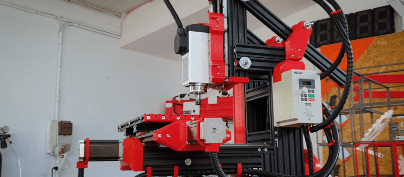
Most DIY CNC milling machines we see use a gantry arrangement, where the bed is fixed while everything else moves around it. On most commercial metal milling machines, the table is the moving part, and are known as knee mills. In the case of [Ivan]’s mill, the table can move 187 mm on the X-axis and 163 mm on the Y-axis. The 1.5 kW spindle can move 87 mm in the Z-axis. All axes slide on linear rails and are driven by large stepper motors using ball screws. The table can also be adjusted in the Z-direction to accept larger workpieces, and the spindle can be tilted to mill at an angle.
To machine metal as [Ivan] intended, rigidity is the name of the game, and 3D printed parts and aluminum extrusion will never be as rigid as heavy blocks of steel. He says claims that the wobble seen on the video is due to the uneven table on which the mill was standing. Of course, a wobbly base won’t be doing him any favors. [Ivan] also had some trouble with earthing on the spindle. He nearly set his workshop on fire when he didn’t notice tiny sparks between the cutter and aluminum workpiece while he was cooling it with isopropyl alcohol. This was solved with the addition of the grounding wire.
While the machine does have limitations, it does look like it can machine functional metal parts. It could even machine metal upgrades for its 3D printed components. One possible way to improve rigidity would be to cast the frame in concrete. [Ivan] has built several other workshop tools, including a massive 3D printer and a camera crane.


>CNC mills will never match real heavy metal mills
Surely you know better than to conflate CNC with DIY in the very first sentence of the article…
Pretty much all modern “real heavy mills” are CNC nowadays
Maybe pop a ‘DIY’ at the very beginning.
Reading further, the issue appears to be some confusion regarding the difference between a gantry router (2.5D) and milling machine (3D or higher).
Whilst pedantulating: Most industrial machines use a cast iron, rather than steel, base. Though steel weldments are certainly becoming more common as the basis of industrial machinery.
Or granite? Or is that only for CMMs?
Granite is for CMMs. Epoxygranite/mineral castings can be found in some (rather hi-end) machine tools, though granite vs epoxygranite is kinda like chair vs electric chair
Would be interesting to see more air or hydrodynamic bearings used to make more frictionless surfaces beside only the spindle bearings say for example in this lathe:
https://hackaday.com/2019/10/31/high-precision-air-bearing-cnc-lathe-and-grinder/
https://hackaday.com/tag/air-bearing/
Another one of those moments where I’m wondering why no one has 3D printed an open source hydrodynamic bearing, as I’ve been planning to do if I can ever get the time to work on the fluid bearings for the turret, or Dobsonian mount design, for the RDF source ID tracking rig
I still need to read into the math regarding scaling from, for example, a copy of a camera tripod mount.
Look up a Light Machines PLM 1000 or PLM 2000 benchtop milling machine. Its frame is some kind of polymer. They have a 100 pound working load and there’s nothing close to them before or since in capability in a comparably sized machine. Thus when they come up for sale they ain’t cheap. The PLM 2000 uses servos on all axes and can be used with just a RS232-C serial connection. The PLM 1000 uses stepper motors and the original control system was a big, separate box, and a proprietary ISA or PCI card. If you have a PLM 1000 without one or both of those components it’s much lower cost to just replace everything except the motors, may be possible to interface the spindle motor controller to new electronics.
Intelitek bought Light Machines, and went on to release the Benchman XT. Granite base, linear rails, servo motors, a great spindle and a toolchanger, all in a benchtop format.
I have the ProLight 1000, it is a great mill. These were used a lot for teaching in the ’90s and are often being sold off after years of light service (or years of being stored because nobody was using it and now somebody wants the space back) by educational institutions like schools, colleges and universities. I picked up mine from UC Davis surplus sales for $1000, complete with control box, ISA card, a period late ’90s computer running Windows 2000 load with software and already configure, and a nice heavy duty cabinet to house everything + tooling, with the mill/monitor/keyboard on top. It also came with a usb 3.5″ floppy drive, which I use to copy g-code to floppies generated on my workstation to load onto the vintage win32 box.
I would like to switch it over to CNCLinux (or it’s successor), but it works fine, and I’ve too many other projects to work on.
Light Machines / Intellitek are reasonably well supported on the LinuxCNC forums, as an ex-Intellitek engineer is active there.
Granite is used on a number of CNC machines, usually not metalworking though the super precision lathe that the national laboratory had was built out of granite i believe. Lots of companies that machine machines that laser drill PCB vias use granite as the support structure which makes for incredibly heavy machines. Granite is about the same density as aluminum. On the PCB drills we make at work we found an alternate to granite which saves a whole lot of weight.
Cast iron is used because of it’s ability to dampen vibrations, it does not sing like steel. You might see steel weldments in CNC machines but they are limited to accessory type items like tool changers. I dont think i have seen one of the big companies use weldments. There might be some smaller companies that dont want to pay for patternwork for castings.
Would lead help in the dampening perspective, if say mixed with granite in a resin/cement?
I wish they would have more people reviewing these articles before publication. I’d be happy to buy a subscription to HaD (similar model to ars would work, rss, no ads and such) if it meant that the increase in revenue from selling subscriptions meant an increase in quality. And decrease in mistakes like this.
Even diy CNC mills can match “real heavy metal mills” for some values of “real heavy metal mills”. Some people out there are building real beats that will happily give your grandpa’s Bridgeport a run for it’s money.
If you look in to how modern milling machines are built you find that many of them are welded from heavy steel profiles. A process that feels more in reach for the home gamer than the traditional big castings.
While not a mill, the PrintNC actually uses a bolted steel frame along with quality hardware (beefy linear rails, ballscrews, water cooled spindle, VFD, etc) and a few 3D printed jigs and less critical components to produce a router that can do an admirable job of machining stainless given the under $2000 price tag. Not a Bridgeport killer, but does really illustrate the value of a full steel frame.
The ideal way to build a welded steel frame CNC machine would be to weld the big pieces together then run it through a heat treating process to relax the stresses. Then rough-in the machined surfaces followed by a second de-stressing. Then do the fine finish machining. Shouldn’t be too difficult to fully automate something like a production line to make welded steel lathe beds.
Recently watched this build and was wondering if lead alone or mixed in with the granite/resin might help dampen. Another one of the hydrodynamic bearing application, somehow like I think about with engines and motors, moments also. https://www.youtube.com/watch?v=FkGdJMVJ1Fc
I’m not sure this can accurately be described as “3D printed CNC knee mill”. Some of the parts that hold the functional parts together are 3D printed. Most of the functional parts seem to be made out of metal or something else and don’t seem to be 3D printed.
My first CNC router had Z axis 3D printed (three times, and one of them was by manufacturer), everything else made of aluminum profiles screwed together with M5 nuts and bolts (no proper nuts for joining the profiles) and two supports for gantry were 3D printed too. The whole thing was wobbly, and when it got stuck, the Z axis twisted…
Yep, shame they don’t offer subscriptions to an ad free version of the site, then they might have a bit more revenue which could possibly prevent issues like this.
I’m running Pi-Hole. Every site is ad free!
So many mistakes in such a short article… and I would question the rigidity of this assemblage comapred to even the average drill-press-with-XY-table never mind an actual mill made of steel or cast iron, even a cheap import one.
Wonder how much he spent on this compared to buying a 2nd hand Sieg or similar?
What’s next? A Lego CNC mill?
He’s lucky he didn’t electrocute himself. Reminds me of the guy who had his girlfriend shoot him with a .50 Desert Eagle using a thick book to stop the bullet. Naturally it did not. But he was sure he’d make a fortune on YouTube.
Many years ago there was one made from wood (chipboard possibly), with some cheap drawer guides instead of linear bearings. It worked good enough for PCB milling, which was the goal…
If you’re talking about the chipboard-and-rail builds from Norbert Heinz / HomoFaciens, I’ve seen (in person) his chipboard machine cutting (slowly) thin galvanized sheetmetal, like the kind that he makes the encoder wheels out of. Yes, you could cut it with tinsnips as well…
Around about this version: https://homofaciens.de/technics-machines-cnc-v3-2-2_en.htm was certainly robust enough for plastic or wood.
For PCB milling, you can almost get away with a frame made of toothpicks, as long as you can get the Z axis dialed in right and the piece held down super flat. Speed is not critical, side loads are minimal.
Here’s two:
https://hackaday.com/2008/02/26/lego-nxt-cnc-mill/
https://hackaday.com/2011/08/20/lego-mill-produces-sculpted-models-with-fantastic-resolution/
I’d be willing to bet that his table is of a similar flatness to his machine base. Aluminum extrusion is not flat.
His aluminum speeds and feeds are clearly wrong, as he acknowledged. I doubt that his finish will improve substantially though as I can see distinct chatter marks when he interpolates the circular paths that suggest either or both a lack of rigidity and backlash. It is likely that he has both, given the aluminum and plastic construction. Even if he could solve those, the machine will never be square because neither extruded aluminum nor 3D-printed plastic have precise dimensions. He might improve on the surface finish, but his circles will never be circular and 90 degree cuts never square.
That said, it’s cutting aluminum and even steel. Just not well enough to justify the time and money he sank into it imo.
“Even if he could solve those, the machine will never be square because neither extruded aluminum nor 3D-printed plastic have precise dimensions”
Ah, but, that can be solved in software. (really, it can)
…says the guy who set up a mill to bore a hole requiring coordinated three axis moves to run the boring head at a non-orthogonal angle to all axes.
That is seriously one of the most impressive youtube videos I’ve run across.
No mills circles are circular, just close… You want better circles you use a lathe (or add an axis to the design so the machine is effectively a lathe as well), want better still you get into a surface grinder with rotational axis..
While I agree the time and effort put into this really wasn’t worth it, as you could have got better parts built with other methods in less time probably, its a neat bit of engineering. That should be able to produce useful parts, eventually…
Looks like most of the imprecision any of the extrusions and 3d prints can have is well accommodated for really, and both can have tolerances well within what you find on purchased mills, especially the small Chinesium ones (I should know I have one, and its pretty damn awful really – but as long as you keep testing dimensions and fits its good enough to get the job done) or the now very worn out but unrestored old iron… Though both the Chinesium and Old Iron models should be vastly stiffer and probably have vastly more power and speed control to get the finish right..
“No mills circles are circular,”
Err, they are if you use a rotary table.
I have both Clausing lathe and mill, neither worn badly, and a Chinese mini-lathe. As has been noted many times, if you tear down the Chinese machines, clean them and adjust them properly they are quite good. And if you scrape them true they will compete with a Schaublin.
As the other metal heads have pointed out, this was a very expensive build for a not very competent machine.
David Gingery’s designs would certainly outperform this.
https://www.amazon.com/Build-Metal-Working-Scrap-Complete/dp/1878087355
I thought the extrusions were really cool when I first saw them, but after I learned what they cost I lost interest. For the price of the parts he could have gotten a Sherline CNC mill ready to run.
That said, I’m sure he learned a lot which is what really matters. There are some things we only learn by making mistakes. I don’t make as many as I used to, but I still make plenty.
With old Iron you are taking a chance, or have to test it out first if its not been reconditioned when you buy it. The ones that really got used might not look bad on the surface but they can be remarkably wonky.
And with my experience the Chinese mill really is garbage, the design itself has some flaws, though fairly minor really – a reasonable cost cutting measure for the most part… But beyond that other than a really quite impressive motor, gearbox, and the electronics – that working head of the machine (on which nothing has yet gone wrong at all) everything is rubbish, needing constant tinkering to approach working with any accuracy. The amount of use I’ve got out of it vs the amount of time I’ve spent making it approach working properly really means I should just have bought a decent European one, even a new one would now be looking like good value… (Oh and this mill wasn’t that cheap either, I could actually have bought a little larger old Iron seemingly in good condition for the same damn price, or much larger for only a little more – but none of those options would quite fit my tiny workspace, and the new small quality European stuff I couldn’t afford at the time (or now))
A lathe is a different story in many ways so I can expect a Chinesium one to be fixable, or even perfectly functional there – they are much much harder to really make terrible, its just a stiffer and mostly simpler and cheaper construction anyway…
In years past I had two Chinese “7x” metal lathes. There are two main design variants of the 7x lathe.
The most common is also the cheapest made. The headstock is commonly mounted with 3 bolts rather than 4. The saddle is “H” shaped. The carriage crank wheel shaft runs through a plain hole drilled in the apron. Induction hardened bed way surfaces may be an option.
I had one of those, a 7×10 imported by Grizzly, serial number (IIRC) 346. Likely from the first year they were imported. I was the third owner and the poor thing had been badly abused. I had quite a bit of damage repair and fixing of original issues. Any of these 7x lathes billed as a 7×10 will have the length measured between points in the spindle and tailstock. With a 3 jaw chuck installed that will drop the usable working length to around 8″. They typically have a speed knob, a rocker switch for power, and a direction toggle switch. The speed knob can be left at any speed, the rocker switch turns it on and off.
My first lathe was one of the other style, a 7×12 (between chuck face and tailstock) bought from Homier Mobile Merchants. Its headstock was mounted to the bed with 4 bolts. Bed way surfaces were induction hardened. The saddle was a full rectangle shape and heavier due to having more iron. The apron was thicker and had two ball bearings supporting the crank wheel shaft. It also had an adjustable nut on the right end of the leadscrew to eliminate any endways movement. They typically have a speed knob that’s also for power (like an on/off/volume control), a E-Stop/arming button, and a direction toggle switch. To use, unlatch the e-stop button cover, set the direction toggle to forward or reverse. Twist the speed knob to turn on and set spindle speed. If something goes wrong, bop the e-stop. Don’t have to latch it down, just push it enough to break connection to stop the motor. The speed knob has to be turned off to restart.
Over the years, in various countries, many importers started out with the better 7x lathe to put their name on, then at some point switched to the cheaper version, lost sales, then went out of business or quite selling 7x lathes.
Harbor Freight still imports the cheaper version, always has, but at some point they started selling a 7×12 (14″ between centers) online only. They have added a chip cover to the leadscrew and I assume the motor controller used is much improved over the plain, rather ugly, and super noisy “chopper” with pitiful low speed torque controller my old Grizzly had.
After all these years reading HaD, you know what I’d really like to see?
An end to 3D printed machine tool articles, an end to people saying the issues can be solved in software, and end to people “akshewally”-ing into diatribes about physical absolutes where nothing is truly flat or etc. Or saying, well, its not ideal, but he learned from it? It’s exhausting.
In place of all that bull, can we get some real articles on building serious homemade mills and lathes from people who are here, capable of actually making something out of metal, and useful, with no more excuses?
Can we get that, please? Seriously, please?
Real investigations into epoxy granite design, versus cast iron (yes, there are people here who can cast iron, I’m one of them) for people trying to decide what actually works? Real spindle comparisons?
We have had projects on here that were expensive, so I see no reason we can’t finally have a serious discussion on building something not half assed, but serious. I can’t find those discussions being had anywhere, and at this point, the people who know enough to do it are out there- but I can’t find any accessible way to bring them into the forefront with a competent technical editor here.
I know there is a large community of people serious about this, but the conversation isn’t coalesced in one place in a digestable format to just cut through the bull and get working. Can we work on that, please?
As someone who said “You can solve it in software” I stand by that. It isn’t just a way to make an inadequate machine adequate, it can also be used to make a good machine superlative. For example mapping a ballscrew or intelligently compensating for thermal expansion of a spindle.
But I am a fan of cast iron too. Here is my CNC-converted 9×20 lathe.
https://photos.app.goo.gl/re3WP8Tjf5BrbMSF9
I would like to think that you can’t tell which of the visible castings are the 6 custom ones I made for the conversion.
And it is also fun (in the context of this discussion about machine tools) to see the difference between a Chinese 9×20 lathe and an old British 9×20 lathe. This is the Chinese tailstock on the bed of its replacement: https://photos.app.goo.gl/fdsNpf639SxkdMdZ8
The difference in the amount of metal considered appropriate is astonishing. But, then, I imagine the difference in the prices would be too. The Holbrook bed depth is getting on for ludicrous.
If you have a documented project, or know of one there is a tipline – submit it, I expect it will get a nice article… If memory serves Dan Gelbt (or something like – sorry If I misremebered the name) that was featured here was all about precision machine tools he built… Very cool stuff.
That said there is nothing at all wrong with 3D printed stuff in the Machine tool world – and its a tech that is really really available now, so seeing successful use of 3d printed parts/accessories for machining really should not be a surprise – ye ol’ make the tool to make the tool to make the tool can largely be bypassed by additive making, and that can only be a good thing..
I really don’t want to have to spend a small fortune and lots of time making everything from the ground up like its 1800 ish when useful, affordable shortcuts now exist. The tooling worth making is the tooling you absolutely can’t avoid, or will get many many uses from.
3D printing foundry patterns to be cast in iron is absolutely a valuable shortcut. It makes core boxes and removable parts simple Boolean ops. And then you don’t even have to worry about how to mske the pattern
The foundry I use charges £10 per kg for castings in iron. Why use extrusions?
Yes, software is fine for some things Andy- like ballscrew mapping, especially against thermal maps. There, it makes sense. What I’m againet is the entire “we’ll ignore everthing sensical about machine design by basing it on plastic printed parts and compensate in software, like for bed warp”
Make something kinematically correct in the first place, there are enough people here who should know basic design principles that we should just stop trying to 3D print a milling machine for real metal use. That’s what upsets me.
BTW- Andy- your linuxcnc polygonal boring rig is awesome.
Using 3d printing to print then cast parts is perfectly sensible. But noone seems to do that. It’s always ludicrous popsicle stick construction or 80/20. Or we say, its for pcbs. I want to see an actual usable cnc metal mill- with servomotors.
The Taig FB group shows custom spindles & frames are being made for small home desktop machines, and they are using DMM servomotors. The base design though can still interpolate at best to 0.002″ round bores even with ballscrews- not good enough for me.
@Foldi- You mean Dan Gelbart’s lathe. I know because I have gotten it featured on HaD before (I think it’s been posted a couple times). I used to post as Drew for years, then someone else started using the name, so I switched to this.
I’m on a few discords discussing machine design- I would like to see a more collective, open source project to do a real machine design, with real capabilities, and explain the steps to getting there. But I feel like HaD has the capability in membership to bring out the people capable of doing it.
OK, I hear you. I’ve set up a hackaday.io project to enable this. The aim of the project is to research hobbyist-accessible techniques for utilizing materials and components in cost-effective manners that lead to appropriate results. It’s day 1.
I hope that over time many people will contribute in both knowledge and experimentation, and that we can build a corpus of techniques that can then be used to design and build good solid machines. Initially, I really want to concentrate on the mechanical foundations of machines – building frames that are appropriately flat, square and rigid, and the principles behind selecting appropriate components such as linear rails and ballscrews.
No material is off-limits, even Al extrusions and 3D-printed plastic, but I hope that we can find ways to design to their strengths and techniques to correct for their weaknesses. I want to see experimentation with cheap granite surface plates as bases, or using 3-plate methods to flatten cheap granite from craigslist-type sources. (Old countertop as a CNC router base anyone?, Reclaimed step as a lathe base?). Techniques to build bases from composites or cast metals. Is $200 spent at the foundry a better investment than $200 spent on extrusions?. Let’s try to answer that question with some evidence, as opposed to logic. Can we true up extrusion to make it perform well? etc.
There is so much to do. I already have more ideas than I’ll ever get to, so I’m looking for any and all volunteers to join the project and contribute. Got a technique itch to scratch? Bring it, and we’ll collaborate in whatever way we can to help you achieve good results and hopefully a ‘recipe’ that others can later use.
Software compensation is definitely in scope, although I’d love to see it from a similar perspective – hobbyist-accessible. Ball-bar and laser interferometry systems are not typically so due to cost. Ideas? Bring them.
Again, I don’t want to build a machine here. I want to compile methods and techniques for building good machines from the time and money invested. If we end up with a set of design principles that people can follow to design and build a capable router using an old kitchen countertop, or a lathe on a concrete-cast base, then great.
I don’t have a time-frame for this project, or a deadline for it to end. All I know is that it’s day 1.
https://hackaday.io/project/180820-hackaday-machine-build-techniques
Well, if the hole is small enough, a drill bit in the mill will create a round hole, but I get your point. But, a lathe or 4th axis can get you truly circular in only one dimension on a part – or at least as good as the bearings and cutting forces allow. In theory interpolation can’t attain the that, but with quality mechanics will get darn close. For instance, some Kerns can maintain +/- 1um on an axis, so an interpolated circle would be within +/- 1.41um of round, which is…good enough… for most. That isn’t supposed to be a comparison (which would be grossly unfair) – I’m simply observing that for many parts on decent mills, interpolation can achieve results that are to all intents and purposes, round, and that my original observations are not unfair.
If we really wanted to nitpick on perfections, I’ll just float the following assertion. There is no truly flat physical surface in existence. We don’t chase perfection because it is unattainable. We shouldn’t use that as an excuse for sloppiness though, especially expensive and unnecessary sloppiness.
I honestly wonder what tolerance this machine could attain, and how that would hold up to thermal and moisture effects. We know that plastics change dimension based upon absorbed moisture, and that 3D filaments absorb moisture. We also know that most plastics have orders of magnitude more thermal expansion than iron and steel, as does aluminum. (FWIW Kern use aluminum, but they thermally model and actively condition their components to maintain consistent dimensions.) I’m more concerned with the build techniques here than the components though.
I just cannot agree with the statement that the builder has accommodated for imprecision in extrusions and prints. It’s obvious just watching the techniques used during construction that is false. No attempt was made to ensure the extrusions were straight or that their surfaces were flat. 8020 lists specifications for those, and it’s not pretty reading in terms of precision machine building. Cheaper vendors don’t even bother with specifications. You would have to sacrifice the black anodizing to improve the extrusions. He cut the extrusions with a non-precision saw, measuring the lengths with a tape measure, good to about 1/32″ accuracy. Only once did I see him cut multiple pieces in the same cut in an attempt to ensure their lengths were identical – and that was for the table, the one place where it probably doesn’t even matter. He hand-drilled into the end of extrusions, even though he clearly owns a drill-press with a movable table where a jig would have made accurate work possible. He center-punched and hand-drilled extrusion to mount his rails, when (again) he could have bolted a jig to the drill press. (That actually isn’t that critical, as those rail holes have clearance, but it would have made his work easier). What does matter is that no straight edge was used during assembly to ensure that the rails were straight, and I suspect that he just guessed what torque setting to use on that Makita, if he didn’t just bolt them as tight as they would go. You can see rail issues when he mounts the carriage on the Y rails – that movement should be silky-smooth, not binding. It doesn’t help that the Y rail separation is set by a length of extrusion at one end, and by plastic at the other – even if he had mounted them straight and parallel to begin with, unavoidable environmental changes will affect both ends differently such that they will rarely be parallel and will thus nearly always bind. Stiction in rails will cause missed steps, poor finishes and loss of correct part dimensions.
There is no evidence of surface plates, straight edges, master squares or gauge blocks which would be needed to tame those imprecisions. None.
Yes, the plastic parts have great aesthetics, and they appear to be very well printed, likely using an expensive 100% infill amount of filament. At this point though, it’s Lipstick, meet Pig. The sad thing is that it’s not the use of aluminum extrusion and 3D printed plastic that’s the problem. It’s the lack of understanding of how to minimize their imperfections to build a good machine from them. It’s like he built a machine to look good on video without knowing how to build a machine that actually is good. The financial investment in this one could be rescued with a few design tweaks and some reassembly involving some metrology.
Final thought for other builders out there – don’t clamp linear rails in metal jaws without soft protection (wood works), and actively cool them during cutting. You don’t want to gouge them, or cause them to warp or anneal.
By accommodate the poor material selection I meant not that they corrected and ground in the extrusion or anything like that – just that the design itself means much of the imprecision gets either averaged out to become less meaningful or reasonably self correcting when the tensioning bits of the assemblies are installed.
Not that its at all a good machine, or even that every design decision is correct – but that its a reasonably well designed construction to get a functional if very slow machine out of the pig swill parts. There are as you point out troubles, but anything built with those parts would have flaws in some area, ultimately its the wrong material choices, or at the very least a failure to add in some off the shelf ‘precision’ metal parts in key areas, and yes many less than optimal building methods too.
Stiction in the rails really won’t matter much – the steppers, basically any steppers are going to be way way over spec for the stiffness of the machine, and probably the spindle too.. This thing is going to be tickling parts to death if it wants to survive the operation and create a part at all close to the right size..
Should also point out I agree the CNC stuff being able to fake a really good circle or even sphere, not really disagreeing with you on that point – more just pointing out imperfect circles even if they are more imperfect from this device isn’t anything new – everything is about being good enough, and this is probably good enough for some folks.
creator put in some hard work on this, but i feel like a couple of welds, some aluminum castings, and some epoxy granite in strategic places would’ve improved the result, and probably been less effort.
but, yeah, converting some sieg would’ve gotten even better results for even less effort.
I’ve converted a G0704 for home use and I have to be pretty dainty with my cuts (though it can handle steel all day). This thing must have cost significantly more and be less capable in terms of material removal. Though I’d give anything for a decent xy envelope.
VMC not knee mill
To nitpick even further than everyone else has already, this isn’t even a “knee mill”. On a knee mill (e.g. the bridgeport series 1 everyone knows and loves), the z-axis is the “knee” below the table moving up and down. Here the z-axis is the spindle moving up and down. That arrangement is called a “bed mill”
Wait, I’m sorry, but did I read that right?
Cooling with… isopropyl alcohol? Am I naive and this is industry practice? Or is it just me that using a rather flammable liquid as a cutting fluid cooling medium is a baaaaaad idea…?
What’s next, cooling with Acetone?
It works and if you manage to get a spark milling aluminum you are really doing something wrong. WD-40 also works great and it’s flammable too. Technically mineral cutting oil is as well. There have been fires but it is pretty rare.
I’ve used WD 40 and can confirm it works great on aluminum. I’ve never considered alcohol. Isopropyl alcohol will ignite at 750 degrees F. Couldn’t find any ignition temps for WD-40. I suppose the low flash point of alcohol would provide cooling benefits, but I don’t consider the benefit to be worth the risk of losing eyebrows (or anything more important than eyebrows). Like the previous commented said; if you’re seeing Sparks while milling aluminum something is very wrong.
“CNC mills will never match real heavy metal mills on hard materials”
Excuse me? One of my first ever projects on my DIY CNC was to chop up a large metal cutting saw blade in to a selection karambit knives. Admitedly a did destroy a few cutters but the tool steel blade I was cutting up was hardened. After sharpening the blades and without any futher heat treating I could easilly score pretty deep lines in glass without any damage to the blade.
Now try doing that on a non CNC heavy duty mill.
What youtube video do you mean? Sounds super impressive