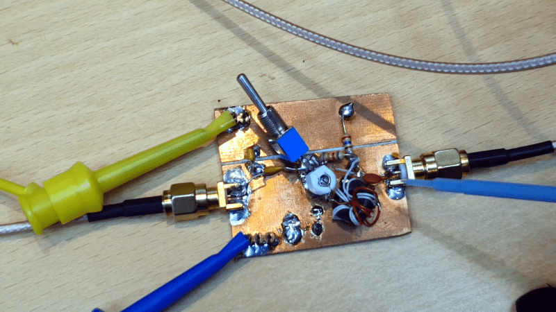
While the Miller effect might sound like fun, it is actually the effect of parasitic capacitance in amplifiers. What do you do about it? Watch the video below the break from [All Electronics] and find out. We like how the test circuit it uses has a switch to put the mitigation circuitry in and out of the test for comparison purposes.
Actually, the Miller effect can refer to any impedance but in practice that is most often parasitic capacitance because of the construction used for tubes and transistors. The sometimes tiny capacitance gets multiplied by the inverting gain of the stage and increases the amplifier’s input impedance. This, in turn, reduces the bandwidth of the stage.
There are a lot of nuances to the Miller effect. Sure, you can neutralize it as the video points out. You can also use non-inverting buffers on the input or output of an amplifier to reduce the effect. Some designers also exploit the effect to convert a small capacitor to a larger one, especially in applications like IC design where large capacitors are harder to make.
Usually, output capacitance is neglected because the total output impedance magnitude is small. But if you do have a high impedance output, it needs to figure into the analysis, too.
We talked about transistor biasing and Miller capacitance came up in the comments. Of course, you got the same effect in the old tube circuits, too.


….”and increases the amplifier’s input impedance”
???
The miller effect multiplies the parasitic base-collector capacitance by the transistor’s gain, resulting in an input impedance with a significant capacitive part (= decreasing impedance at higher frequencies). Effectively, the input impedance at low frequencies is just it’s small signal input resistance (R_pi) but at higher frequencies the input impedance is reduced by any capacitance seen from the input.
After neutralizing the base-collector capacitance, this capacitance (although there are others, such as the base-emitter capacitance) no longer reduces the input impedance at higher frequencies, thus resulting in a higher input impedance.
I think calling it increased impedance is misleading. Capacitive reactance has frequency dependant impedance and I would have just called it reduced bandwidth(in the case of audio amplification, though if you were trying to amplification a specific frequency for a different application then I might refer to it as impedance)
The input impedance is directly limiting the bandwidth here, otherwise the neutralization wouldn’t have significant effect.
The miller effect multiplies the base-collector capacitance, which results in a large equivalent input capacitance. This input capacitance together with the source impedance will result in frequency dependent voltage division (R_source and C_equivalentInput) which is the bandwidth limiting factor here. If you drive this amplifier with a perfect voltage source, then neutralization would be unnecessary as an ideal voltage source isn’t bothered by the additional input capacitance.
I agree that impedance makes more intuitive sense when talking about a specific frequency. Perhaps instead of increased input impedance, reduced input capacitance is a better description. However the reduced input capacitance / increased input impedance directly causes the increased bandwidth so IMO it’s the most important piece of information.
If you’re driving a very large capacitive load, then the output would be the bandwidth limiting factor. In that case miller neutralization won’t help you, even though it ‘increases bandwidth’ (but only when the input is limiting the bandwidth).
thanks for this article – coincidentally just what I was after.
I really like this guy’s youtube channel.
Only watched 2-3 videos of his channel so far, and WOW!
High quality videos with well explained topics. Subscribed.
Thank you!
:o)
Excellent explanation!
+1
Clear and concise. Even a caveman would understand.
Doors and corners, doors and corners ..
Oh wait, not that Miller
That is a neat little trick!