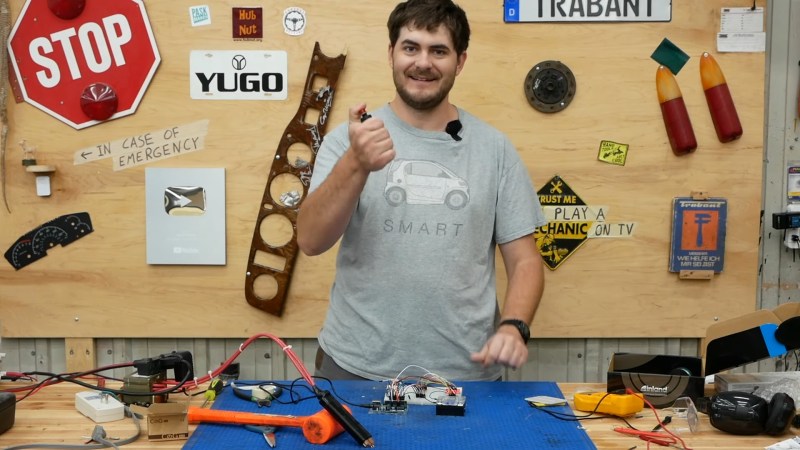
Raise you’re hand if you’ve ever soldered directly to a battery even though you know better. We’ve all been there. Sometimes we get away with it when we have a small pack and don’t care about longevity. But when [Robert Dunn] needed to build a battery pack out of about 120 Lithium Ion cells, he knew that he had to do it The Right Way and use a battery spot welder. Of course, buying one is too simple for a hacker like [Robert]. And so it was that he decided to Build a Spot Welder from an old Microwave Oven and way too much mahogany, which you can view below the break.
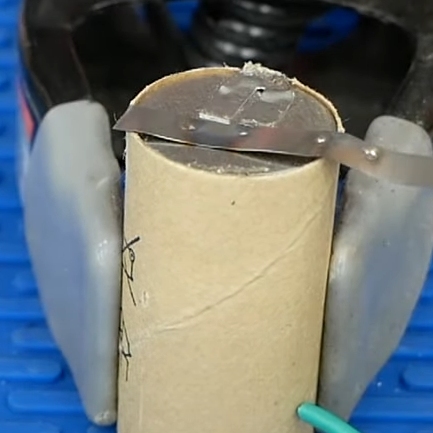
For the unfamiliar, a battery spot welder is the magical device that attaches tabs to rechargeable batteries. You’ll notice that all battery packs with cylindrical cells have a tab with two small dimples. These dimples are where high amperage electricity quickly heats the battery terminal and the tab until they’re red hot, welding them together. The operation is done and over in less than a second, well before any heat damage can be done. The tab can then be soldered to or spot welded to another cell.
One of the most critical parts of spot welding batteries is timing. While [Robert Dunn] admits that a 555 timer or even just a manual switch and relay could have done the job, he opted for an Arduino Uno with a 4 character 7 segment LED display that shows the welding time in milliseconds. A 3d printed trigger and welder handle wrap up the hardware nicely.
The build is topped off by a custom mahogany enclosure that is quite a bit overdone. But if one has the wood, the time, the tools and skills (and a YouTube channel perhaps?) there’s no reason not to put in the extra effort! [Robert]’s resulting build is almost too nice, but it’ll certainly get the job done.
Of course, spot welders are almost standard fare here at Hackaday, and we’ve covered The Good, The Bad, and The Solar. Do you have a battery welder project that deserves a spot in Hackaday’s rotation? By all means, send it over to the Tip Line!


After the 3:15 welding stuff doesn’t he short all the laminations? I thought the laminations were supposed to be electrically insulated to reduce loss from eddy currents. At that specs would that be considered negligible?
Correct. But it was already shorted from the factory, so no way of reversing the damage. It’s a cheap way to manufacture a transformer and the producer of the microwave does what he can to save on copper and iron and the losses doesn’t matter since it’s the customer that is paying the electrical bill and the producer that is paying the shipping bill. The transformer need to be actively cooled since the no-load current is astronomical high (again, it has way too little copper and iron to really function well).
I would have spared all that copper by just sticking two copper nails at the end of the cables. With the handle around they would have looked nicer and less bulky. Do you see any possible drawback?
Sorry, I didn’t mean to post this as a reply…
they would heat up insanely after a couple of welds. This is what many cheapo china welders do and it makes them impractical for anything other than 1-2 cells at a time.
So is the extra copper in the handles to dissapate heat then? Or to keep it all low resistance until the very last possible moment with the short tips?
I’m still not convinced. Why should only the last part of the cables get hot? I mean, if you say that the needles get hot and they transmit the heat to the cables, it makes sense, but the heat should easily dissipate through the cables because there is no discontinuity of any sort.
Resistors add up in series and the power dissipated in them is, well you know Ohm’s law. So if the cables get got during welding, the low resistance handle would stay cooler; but since the time of each weld is so short i don’t expect the cable to become hot. 3dPrinting a PETG handle for the cables directly should probably just work as well and save time and money, but it sure wouldn’t look as cool ;)
I’m using a 12v car battery with a motorbike relay controlled by arduino. At 100ms my probes would probably go straight in the battery i\m welding. 30ms works great, doesn’t heat up the parts between the spots.
Hmm. Why take the core apart? The original secondary could also be removed with a hacksaw or a chisel.
That’s what about half the comments say too. I assume the instructions he followed didn’t have that, and without knowing more about transformers it’s not obvious that would be any better.
I’ve done both methods with MOT breakdowns, and I have to say that the method he used was far simpler and less messy. I’ve removed 4 or 5 secondaries by cutting and then knocking them out, and it was very messy!
I have build such a spot-welder. It does not do the job!
I have a transformer from a microwave-oven, an high current (160A) triac, microcontroller with a 16×2 LCD and some switches / wheel-encoder for time-settings and single/double puls.
The problems:
– the transformer must be per-magnetized, so that this is not necessary any more
– the current on the 230V line was very high, I had a 25A fuse for the line and a 35A fuse for my house. (Sometimes it worked, often the 25A fuse blows and sometimes the 25A and the 35A fuse blown at the dame time)
Solution:
– use an adequate DC power-supply (I use current limited StepDown-regulator to create the load voltage)
– use capacitors (several 100F/2,7V types) in parallel and two in a row
– create a board with 8x N-Chanel MosFETs which can switch each 300A
– add cooper wires and two pipes for the hand-tool
– I have add a 10k resistor, so that the micro-controller can register a short circuit, if the cooper-spikes are pressed on the metal from the LiIon-battery
pre-magnetized
fuses blown at the Same time
I too built one of these microwave oven transformer spot welders and I was disappointed with the results. In my case a 555 timer provided the pulse timing. It was certainly powerful enough to make the welds, but it was very inconsistent even with a constant weld time.
I suspect that without synchronizing to the AC waveform, simple timer based welders aren’t going to be consistent. In the end I scrapped the crappy welder and bought a Kweld unit which is fantastic.
I also bought a Kweld, and after using it with a proper supply I will never go back. You’re right about the AC waveform – it isn’t a constant current flowing which makes timing near meaningless.
While a knockoff KWeld could certainly be simplified to approach the cost of these homemade microwave units (eliminate current and voltage feedback, just use some of the IGBT’s used in the KWeld, etc) the extra features are certainly worth the increase in price IMO. Directly setting the weld energy in joules and not having to worry about timing, voltage, current, etc is just awesome.
I’ve made one like that as well with a 555 as a one shot to switch the mains in through using zero crossing opto coupler triac driver. And in a nice wooden box like the video.
The zero crossing causes havoc with the timing but fir the few packs I make it’s adequate and I can live with the inconsistency.
Chopping the secondary winding out worked fir me rather than cutting the core.
> I suspect that without synchronizing to the AC waveform, simple timer based welders aren’t going to be consistent.
AC is 50-60hz, meaning you get power cycles at double that frequency. In terms of milliseconds, that’s half of 16.7 – 20 ms, or 8.3 – 10 ms. For timings over 50ms, I don’t think AC should be a factor.
If you are concerned about it, then I suppose you could have your microcontroller monitor the AC waveform with an input to find the zero crossing and start the timer synchronously.
I know I’ve seen The Post Apocalyptic Inventor (or maybe Great Scott?) do zero crossing detection with an Arduino safely somehow, so I imagine if the timing was based off starting at a zero crossing it might be more consistent?
A design I remember seeing somewhere had the power switching on primary side, and had counter of half-waves. So you could select 1 to 50 half-cycles of AC delivered to the transformer. Primary side switching also reduces the transformer heating.
Ooh that’s interesting. Robert already had his SSR on the primary side.
I’ve bought an off-the-shelf kit for making a MOT-based spot welder and I’m happy with the results, the welds are reasonably consistent. So far I’ve used it to put together a 42-cell pack for an ebike, I’m just preparing to make another one.
The kit uses a solid-state switch to switch power to the transformer on the primary side. Time is adjustable in 10ms increments so it’s most likely switching on a zero-crossing. The current is somehow adjustable too, I haven’t investigated how – but it works.
This seems to be the same as the kit that I’ve used:
https://www.lazyliving.co.nz/diy-spot-welder-kit
one word:
kWeld
I’ll raise my hand, in that I used a standard MIG welder once to quickly spot weld a broken tab back onto a NiMH cell for a tool battery. I will never do it again, and that battery has been in service for 5 years since then.
Lead acid battery, starter solenoid, cheap timer module to set pulse interval, cheap power MOSFET module to drive starter solenoid, momentary SPST pushbutton switch.
I can’t decide if I like the safety profile of a lead acid battery (finite though large amount of power, dc) or mains (fused, maybe even gfci, but AC) better…
I will join with the minions and say that this is silly.
I took my (very simple) old thermocouple welder and converted it to a battery welder in about two hours and a few USD in materials.
My new thermocouple welder is, in fact, a bit silly. Controlled by a teensy 3.5, a touch-screen, and 2Mbytes of look-up tables (T/C type vs awg vs electrode temperature vs contact resistance vs capacitor bank output R) in flash. In my defense, I was getting frustrated with increasingly inconsistent welds when I had to do on the order of tens of T/C junctions at a time (do not ask – it was an insanely stupid and unnecessarily complex science project designed by the neighbor’s kids).
1) I know how to READ, Hackaday.
2) My computing equipment archives text-based material much more efficiently than videos.
3) Retrieval of rationally-produced text-based information is a random-access process; that of video-based is–inherently–a painfully slow sequential-access process—just like accessing information stored on tape.
I ‘do’ YouTube’ for music and entertainment. I do not rely on YouTube for the obtaining of any serious technical information.
Raise you’re hand if you suck at grammar
I try, but it is only possible for me to make a spell check in Firefox.
How many transistors does it take to make a single pulse? Two? Fifty? 100,000? I think I would not bother with a microcontroller of any kind. I would instead use a 555 timer circuit, because I have one handy. Also, I am pretty sure a 100W transformer would be all I need for welding something as thin gauge as battery terminals. A single triac would work just fine for switching, as it turns off by itself at zero current. I may be old-fashioned, but I don’t like introducing complexity without a good reason.
@Matthew Morycinski – But with a microcontroller you are able to recognize that both contacts are in a short circuit (contacting the metal) and then it is nice if you get an automatic pulse after two seconds. This is a nice feature. Or two pulses or a longer pulse. In my case the capacitors must be full till I can make an other pulse. I have there a LED what lit up if the capacitors are full. I need a protection, the double layer capacitors should not get a negative voltage, but this can happen it the capacity of one capacitor is a bit lower as the other capacitors. So I created four switchable resistors to reduce the risk of under-voltage damage.