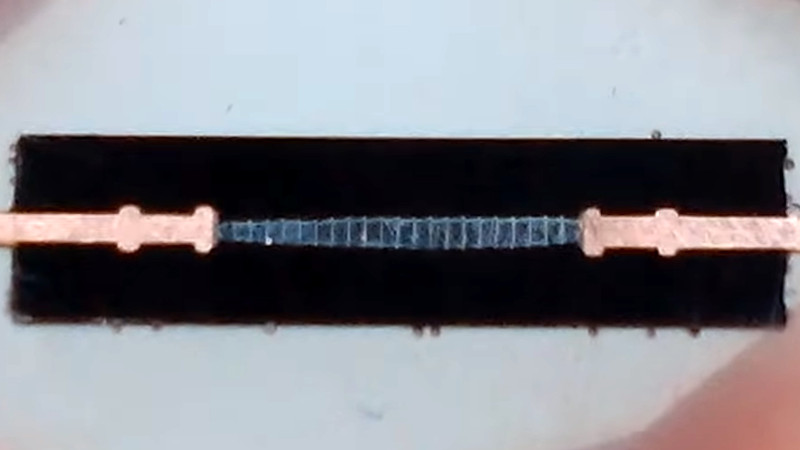
When we use an electronic component, we have some idea of what goes on inside it. We know that inside a transistor there’s a little piece of semiconductor with a junction made from differently doped regions etched into it, and in a capacitor, there will be metalized plates on the surface of some kind of dielectric. Reverse engineering has given us extensive die photography of integrated circuits, but there remain a few component mysteries to be uncovered. One is laid bare by [WizardTim], as he cross-sections a 20KV high-voltage diode.
A conventional low-voltage silicon diode has a forward voltage drop of about 0.7V and a relatively low maximum reverse voltage, for example with the 1N4001 rectifier it’s 50V. For the higher-spec 1N4007, the reverse voltage rating is 700V. This diode has a 25KV reverse voltage, and a clue to its construction comes in its quoted 45V forward voltage. Sure enough, when mounted in resin and carefully sanded and polished flat it reveals its interior as a stack of diodes in series to increase the reverse voltage at the expense of forward voltage.
Revealing the inner workings of an unusual component is fascinating, and the lapping technique used is definitely worth a look. It’s something we’ve seen before, for example in reducing CPU thickness for increased performance.


Have had success connecting a low of avalanche diodes in series to make HV stack – tough with way higher current ratings than dinky monolithic devices. It seems sensible, when stacking them, to err on the cautious side and make the stack have excess holdoff. You’re playing with stats, and if there’s 100, then the weakest percentile is likely present…
Soft recovery diodes are good too but not for repetitive high frequency use. To go really fast, you have to balance the parasitic capacitance (which varies between items and with voltage and temperature) with each other. Perhaps adding a bit of extra capacitance which may or many not hamper response itself.
Regarding the oddly high voltage drop. Suspect it’s the resistance of the device plus the voltage drops of the devices. If there’s 20, that should be 14 V, leaving about 30 V more for the resistance. At 5 mA, that’d suggest 6 kohm. Seems high nevertheless. Maybe the drops are larger and the resistance is less?
You can get more devices with much lower forward voltage. Part numbers not to hand, but have some in a box. Pretty sure they’re rated a much larger fraction of 1 A.
1N4007 is 1 kV.
Indeed. 1kV max peak repetitive reverse voltage. 1000 × √2/2 ≈ 700Vrms
45V forward drop is a small percentage of loss for 20-ish kV.
But it gets hot and needs cooling.
If you’re pushing enough current at 20kV that the forward drop is a significant cooling issue.. you have my immediate attention.
There are cases where you need to hold off a high voltage in one direction but pass a high current at lower voltage in the other direction. One that comes to mind is certain kinds of gas discharge lasers, which need a high voltage well into many kV to start but only a few hundred volts to continue operating.
In my experience, you typically need two circuits to deal with this issue. One circuit for a higher voltage ‘ignite’ followed by a drop down to lower voltage higher current ‘sustain’ operation. Typically it isn’t too easy to have, say, a 15kV circuit work efficiently down at 2kV sustain voltage.
“What goes into a high voltage diode?”
…electrons!
Hello Everyone,
I work for a company that manufacturers high voltage diodes her in the United States. I can confirm that typical high voltage silicon diodes use multiple silicon wafers stacked in a single device.
With regards to breakdown voltage ratings – we do normally have about a 1kV breakdown per wafer and we like to put in some extra as a buffer. Typically with a HV diode, if you go into breakdown voltage, you have a catastrophic failure. There is typically just too much power dissipation (heat) and the thing melts.
For VF, keep in mind that most of these wafers are not your typical PN junction. A ‘normal’ PN junction will not be able to handle 1kV standoff voltage or be quite as thick as you are seeing here. Also, the faster we make a diode junction, the higher the VF is going to be. So a normal recovery diode (<3000ns TRR) might be 0.7V – 1V VF depending on the current, our fastest diode (<30ns TRR) might have double that, or more.
Let me know if y'all have any other questions about HV diodes that I can help answer.
Hey Dan, got a question about a diode I’ve found working on an oscilloscope, it’s about the size of a rice grain, the schematic says it’s a Y16GA. I can’t get a reading on it with my DMM. Can you help me with some details on that diode and how to test it? Thanks!
And why do we say that power diode can support high voltage and current?