It’s common wisdom that the lathe is the essential machine tool, and the only one that can make copies of itself. While we won’t argue the primacy of the lathe in the machine shop, this scratch-built, heavy-duty lathe gives the lie to the latter argument — almost.
We’re used to seeing homebrew lathes, of course, and we’ve featured more than a few of them before. But two things make [Jornt]’s build stand out: how few specialized tools were needed to build it, and the sheer size and bulk of the finished product. Where most homebrew lathes tend to be the bench top variety and feature cast aluminum parts, [Jornt] went with steel for his build, and a lot of it. The base and bed of the machine are welded from scrap steel I-beams, and the ways are made from angle iron that has been ground flat with a clever jig to hold an angle grinder. The angle grinder plays a prominent role in the build, as do simple tools like a hand drill, files, and a welder — and yes, the unfinished lathe itself, which was used to bore out the bearing blocks for the headstock.
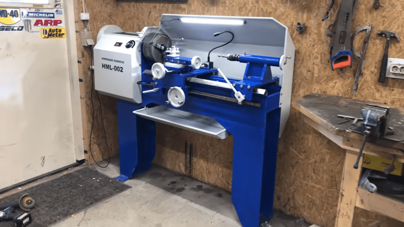
The completed lathe, powered by a treadmill motor in a way that [Jeremy Fielding] would no doubt endorse, comes in at a beefy 450 kg. It honestly looks like something you could buy from a catalog, and has most of the features of commercial machines. One thing we’d love to see on this lathe is the electronic lead screw that [James Clough] developed for his off-the-shelf lathe.


Beautiful work. Quite a commitment and skilled execution. The els would be a great addition.
At just over 1000 lbs it’s not real heavy metal. Here’s on where the machinist rides the carriage:
https://i1.wp.com/makezine.com/wp-content/uploads/2011/11/enormous-lathe-614×443.jpg?resize=614%2C443&ssl=1
I used to work at a company that made production line grinding machines. The beds were solid cast steel, many tons, annealed for months. 0.0000001 (one millionth) inch accuracy grinds on oil drilling parts that weigh hundreds of pounds. The chuck for a hundred pound part is a major engineering challenge all by itself. We needed special gear to pick up and haul the beds around, much too heavy for standard fork trucks and hoists. Every shipment went out the door on an “oversize load” truck with a lead car and lots of flashing lights.
Got any links to tech info etc. or specs?
Still in business? Curious
I’m curious about the recurring insistence on prismatic ways. A lot of lathes were built with flat ways, using the front edge of the flat ways as the reference for the carriage. This vastly simplifies fabrication, especially if you decide to use a piece of precision ground flatstock as the bed ways on which the carriage runs.
After very significant use you can wear the front edge, which means you have to tighten the carriage gibs (and since it’ll be uneven wear it’ll mean you’d have to readjust the gibs for operation outside of the worn area.) But if you use a chunk of steel 20mm thick, that’s more wear area than prismatic ways have, so it should outlast them. Plus it has the huge advantage that regrinding the bed is trivial, with a single setup on a grinder that can handle top, front, and back way edges (where the gibs bear.) Also vastly easier to scrape true if you’re That Kind Of Person.
So what’s the draw of prismatic ways?
(I mean part of this is bias as my lathes are flat bed and it’s worked really well.)
With a vertical reference edge, something needs to pull the carriage up against it. With prismatic, gravity does that.
That said, I don’t know anything about lathes other than how to turn a really rough prototype on one, but that’s the most obvious benefit of a prismatic way to me.
A couple master toolmakers I’ve known use Hardinge HLVH precision toolroom lathes with flat ways. If it works for them, I’m sure I’ll never have any problems with them.
The HLV-H has dovetail ways, not flat (box) ways. That makes a substantial difference.
And yes, they are very nice – the undergrad machine shop in our department had three of them while I was there.
Prismatic ways wear straight down so the wear doesn’t affect the straightness.
This is the most impressive DIY lathe build I’ve seen. Clearly a lot of thought went into the design.
However, I was disappointed that the alignment of the spindle and tailstock with the ways did not appear to have been done with any degree of precision. Nor was the alignment of the front and rear ways. I suspect that it’s not all that precise a machine. The wobble of the drill bit when drilling using the tailstock is indicative of considerable misalignment between the spindle and tailstock axes. With the workpiece rotating the drill *always* follows the axis of rotation. So the tailstock and drill wobble.
That said, a good machinist can do quality work on a completely worn out lathe. It’s just very slow and requires lots of measuring and adjusting to make precise parts.
A much better way to bore the headstock for this design is to mount the front and rear bearing plates, mount a temporary boring bar on the cross slide and carefully align it parallel to the ways. Then feed the rotating boring bar into the work to bore the holes. That guarantees they will be coaxial and parallel to the ways. Then use the same setup to bore the tailstock bore. (c.f. David Gingery’s book for more details).
A welded build like this is going to move around like mad as it ages. It would really be a good idea to build an insulated box, build a large fire under the lathe and anneal it before making the spindle and tailstock bores.
The beauty of the Gingery design is that you do not have the temporary headstock perfectly aligned with the bed. As it is rotating, and you are moving the carriage along the bed it bores the headstock parallel to the bed. Then you use main headstock to bore the tailstock, again moving the tailstock along the bed, so it is again very parallel to the bed.
Have a look at the book “Foundations of mechanical accuracy” if you are really interested in why a [well made] prismatic bed is slightly more precise than using a straight edge. In some countries (Europe mainland) the reference design for a lathe is with prismatic ways, in England the traditional design is flat bed with front edge reference.
I second this recommendation. There is a pdf floating around, but you can still buy the book (it is absolutely phenomenal) directly from Moore.
That book should be required reading for anyone serious about building real machine tools. I have a copy on my shelf. Holes Contours & Surfaces is an excellent primer as well for more specific things.
Machine Tool Reconditioning by Connelly is also very useful in understanding things.
Other ELS options exist.
Just saying :-)
One here (the designer / vendor is active on the LinuxCNC forums)
http://www.autoartisans.com/ELS/
That said, it seems like a pretty trivial Arduino project. If i was making one I think I would use decade thumb-switches to dial in the pitch. Just because I like them :-)
Good point. I can not understand why this Clough ELS gets mentioned, it is so limited and badly written.
Good old Artisan ELS is miles ahead even with its limitations on how steppers get synced to spindle.
Great build, but bending down to look at what you’re cutting with your angle grinder in direct line of fire isn’t the greatest idea. Not even going to dignify that “angle grinder table saw” deathtrap with a critique.
Ugh. There’s always one in the comments…
I’m not sure what to think of this.
The cost to benefit ratio is a bit low on this project, and in the end it’s not a very good lathe.
The welded steel will warp over time without heat treatment, and the carriage does not fit very well on the bed, which you can see in the wear pattern on the bed guides near the end of the video.
It’s also a pretty much a “standard lathe”. By building the carriage a bit different It already would have been a good X-Y table as a starting point for a mill.
But it does have a bunch of good points too.
First, the act of putting something like that together with basic tools is double plus good for effort.
It is a usable lathe in the end.
I really like the hinged “double half nut”. Simple and effective.
I like the real tool sounds much ore then the “music” in some of the other video’s. I had to turn the sound of for those.
Some idea’s that may be worth considering:
Clamping some sandpaper to the bed, and rocking the carriage over it is a simple way to improve the fit, and with more bearing surface area reduces the wear over time. (Scraping this thing is not worth the effort because of the weld & warp issue).
Mild steel on mild steal does not have good wear properties. A simple way to improve on this is to glue (loctite or epoxy) brass strips to the carriage. Or use hardened steel, for example from a (stainless) steel ruler, either on the bed or under the carriage.
If you do tapers a lot, then make and adapter that works with a cordless drill for the cross slide, just as you did for your first lathe build.
I was also pretty amazed by the build (and drawings) of the Crosskart/Dune Buggy. https://www.youtube.com/watch?v=UNtU9cK6ONU
I agree with this – the cost/benefit is pretty low for most people, we live in an age of plenty where it’s probably cheaper for most people to buy a new import lathe or crusty 2nd hand lathe than try to buy the raw materials & parts to make one.
Starting with even a very poor unit and fixing/improving its shortcomings / wear / damage would likely result in a far better end product as the vital main parts would at least be solid castings even if surface finishes may be junk and components like bearings and screws may want replacing with higher quality parts.
I guess it depends if the goal is to have a lathe or to learn how to build a lathe, nothing wrong with either.
Very good
I don’t think thoes ways are angle iron
“A welded build like this is going to move around like mad as it ages.”
I see a similar comment down below, and don’t understand the mechanism for it. I’m apparently bad at searching, since I haven’t been able to dig any further information up.
Could somebody explain why this happens or what the phenomenon is called so I can look it up? I know welds warp/move during cooling immediately due to differential heating/expansion from the welding process, but I don’t see why that would cause things to additionally warp over the long term.
Thanks!
Impressive build and I love DIY projects like this ,but one thing is missed….steel on steel as a bearing surface is terrible…galling etc…
Last year I built a CNC with bright steel ways with cast iron and bronze sliding surfaces….
bright steel ways are relatively straight and where bolted down…NO WELIDING because of warping…
the tops where hand finished with a surface plate and glued on sand paper….1 year in and works tops….
Thanks