In the world of the cockpit simulator hobby, no detail is too small to obsess over. Getting the look and feel of each and every cockpit control just right is important, and often means shelling out for cockpit-accurate parts. But not always, as these DIY magnetically captured toggle switches show.
Chances are good you’ve seen [The Warthog Project]’s fantastically detailed A-10 Thunderbolt II cockpit simulator before; we’ve featured it recently, and videos from the ongoing build pop up regularly in our feeds. The sim addresses the tiniest of details, including the use of special toggle switches that lock into place automatically using electromagnets. They’re commercially available, but only for those with very deep pockets — depending on the supplier, up to several thousand dollars per unit!
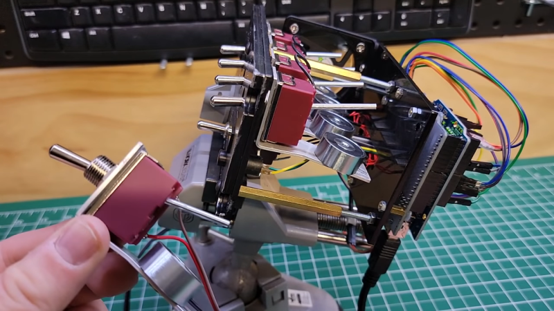
The homebrew substitute is mercifully cheap and easy to build, though — a momentary DPST toggle switch is partially gutted, with a length of nail substituted for one of its poles. The nail sticks out of the back of the switch, where a bracket holds a small electromagnet. When energized, the electromagnet holds the nail firmly when the switch is toggled on; the simulated pilot can still manually toggle the switch off, or it can be released automatically by de-energizing the coil. Each switch cost less than $20 to make, including the MOSFETs needed to drive the coils and the Arduino to provide the logic. The panels they adorn look fantastic, and the switches add a level of functional detail that’s just right for the whole build.
Thanks for the tip, [Mark].


Grace Hyper
Grace Hopper?
I’m glad I wasn’t the only one getting tripped up trying to read the title.
A-10C Warthog Yaw / SAS Panel Panel USD $22.61 from:
Tek Creations
Parcel Locker 10027 44615
Shop 158, 227 Belmont Avenue
Cloverdale WA 6105 Australia
https://tekcreations.space/product/a-10c-warthog-yaw-sas-panel/
His homemade aluminum plate was $4, and the engraving looks perfectly identical to the expensive plastic one.
Of course the panel isn’t really the focus here, as that’s probably the easiest part to reproduce, be it plastic or aluminum.
Awesome tinkering!
My car’s dash board would be way more interesting if it’s switches could move by themselves like this.
Christine!
Added to watch list.
Very cool! :)
I would ask why not use momentary contact and relays.
But I expect having the capability for a quick visual scan of systems status is rather important in a weapon platform such as the A-10.
Any bat out of position is an easy flag to notice and has a positive, manual, override capability.
It’s a simulator. It’s upposed to simulate the actual airplane, where it was made in that way.
Very cool. I can not think of need but very cool to store away.
Wymiary not red switch+ magnet No silikon for control
Fascinating project and excellent craftsmanship.
Regarding the overheating electromagnets: If they were spec’d properly, I’m not sure why they would overheat. (Perhaps these were intended by the manufacturer for low-duty cycle use, or they are AC electromagnets, which will often run hot if you drive them with DC.)
I would suggest epoxying/soldering a small steel washer or–better yet, a steel “knockout” from a outlet box– to the end of each nail “armature. This “paddle” will provide a more significant mass for the magnet to attract, it’s shape will help close the magnetic circuit when the paddle lies against the magnet, and it will almost certainly result in a significant improvement in holding force.
Having achieved this, he can then introduce a current limiting resistor in series with each coil. The holding force will be reduced by the resistor, but overall will still be as good or better than it is now, AND the coil will run much cooler.
“Properly spec’d” depends on the circumstances. In a closed box, you have to de-rate the components quite a lot.
That said, a far better idea would be to use a spring loaded solenoid to capture the end of the stick behind a small bump. That way the only time you need to power the thing is to release the switch, not to hold it in place.
And if you want to make it simpler: a small button magnet on the end of the stick
The magnet sticks to the iron; powering the coil reverses the field and makes it release, throwing the switch the other way. It’s the basic mechanism of a latching relay. You can also make it work both ways by adding another electromagnet on the top side and removing the original spring, so you can program the switches on and off.
Just got to glue a bit of rubber on the magnet so it doesn’t strike metal against metal.
I would use a servo, capable of moving the switch in any direction. That way it would only consume during change, and not continuously.
Waste of a good servo, and not very robust.
I guess thats what the fan is for?
electromagnets should be powered the same as relays, there is a higher pull in and then a lower hold. I saw an Arduino on the back side so he should be able to pwm the coils to 100% to pull in then reduce to hold.