VHDL and Verilog are hardware description languages, used to describe and define logic circuits. They’re typically used to design ASICs and to program FPGAs, essentially using software to define hardware. However, [Tim] has done something altogether quite creative, creating tools to take VHDL and Verilog and spit out PCB designs for discrete logic.
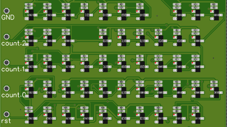
Yes, you read that correctly. The basic idea is to take VHDL source code, and then make a PCB layout that implements the desired logic using resistor-transistor logic. From there, the PCB design files can be shipped off to a manufacturer for pick-and-place assembly at a fraction of the cost of producing a bespoke ASIC.
The drawbacks are obvious; tons of individual discrete parts are required, the size penalty is hilariously bad, and power usage is almost certainly orders of magnitude higher than doing the same logic on an ASIC or even FPGA. Oh, and everything’s much slower, too.
However, as an academic exercise or simply for fun, it’s an awesome bit of work. The idea that one can define a complicated logic circuit and have a PCB implementing the logic whipped up by automated tools is amazing, and we absolutely want to see more of this type of thing.
We’ve seen similar work done with VHDL synthesis into 74-series logic design. If you’ve been developing your own fancy digital-logic-fu, be sure to drop us a line!
[Thanks to Yann Guidon for the tip!]


And look at his GitHub project too !
This picture https://raw.githubusercontent.com/cpldcpu/PCBFlow/main/Images/mcpu_routed.png would have been much more “speaking”, as it looks a lot like how FPGA are configured.
Bonjour, my French friend. The term you wanted was not “speaking” but rather it is “telling”.
L’anglais est excessivement compliqué.
Oh, that’s right, thanks :-)
I wonder if he could’ve used transistors that include the bias resistors. That would’ve made the board a lot cleaner.
He would be much better off with MOSFET. You can eliminate the input resistor and have a much larger fan-in as MOSFET have high impedance inputs.
Also should think about implementing pass transistor logic that are simpler than traditional approach. e.g. an AND gate is just 2 transistors in series instead of INV(NAND(A,B))
Unfortunately, the availability of discrete NMOS transistors is not that great.
https://hackaday.io/project/175015-discrete-nmos-logic-in-2020
But the main reason for choseing RTL (as pointed out by Yann already) is the transistor cost. MMBT3904 clones are simply the cheapest transistors you can buy.
Digi-Key has tons of 2N7002 MOSFETs in stock: https://www.digikey.com/en/products/filter/transistors-fets-mosfets-single/278?s=N4IgTCBcDaIOwAYEQLoF8g and mostly in the same SOT-23 package.
Sure but this might not be available directly at the factory. His point is : the fab house makes the whole thing, automated, for cheap, “look ma! no tedious soldering!”
Buying a reel, delivering it and soldering all the parts is cumbersom and removes the alluring aspect of the project: that all is managed at the fab house for cheap and without human intervention. Even having a few more references, to cut the number of parts, will increase the cost…
Discrete MOSFETs also have a drawback : the speed is inversely proportional to the pull-up resistor and voltage. To get good speed, the circuit will draw quite a lot as half of the pull-ups have to be grounded (on average)
Of course complementary FET (CMOS pairs) is idea (speed and power) but N-FET are much more expensive.
So yes, it’s not possible to have all 4 : price, speed, power, convenience…
> manufacturer for pick-and-place assembly at a fraction of the cost of producing a bespoke ASIC.
Discrete RTL density isn’t worth writing home about. If it were some mickey mouse logic, there are the usual logic families. MUX is one way to minimize having to stock multiple types of logic gates. You pay a lot more for parts, PCB, assembly cost, board space and case just to save on a $1-$2 CPLD!?
ASIC is not the only way to implement simple logic. Flaw argument right there.
Discrete RTL aren’t exactly speed demons either, so likely be sub MHz speed. They can be replaced by the usual $0.03 – $0.30 microcontrollers.
BTW you are going to have a lot of fun time implementing logic that requires some kind of flip-flop… e.g. anything non-trivial designs that have a state machine, counters, clocks.
You should read the project, and even join us on the public TTLers chat room, to see how he addresses these arguments. Short version : he also implements MUX logic with SC70 parts.
His point is not performance, but opening new fronts, explore what can be explored and have fun ;-)
Why not a CMOS design output?
it’s costlier per gate. His point was to go to the cheapest part that was still in stock.
I have played with discrete CMOS and the P-MOS FET are … /expensive/ :-/ which removes quite a lot of the fun.
Fantastic! Now, I heard a while back (2017? 18?) that someone had built a tool to translate Matlab code to verilog or VHDL, so in theory you could now cascade these, and see your Matlab scripts rendered in discretes!
Sure, but then : what could generate Matlab code ? ….
Why stop there ? ;-)
how many toolchain layers before you can compile something from C/C++/ArduSketch (I refuse to call it ‘Processing’)(which is just a specific case of C++ libraries, fight me) and have it spit out something with a working ADC >600samples/sec? would an ADC be a VHDL-described module that it could incorporate into a larger design?
VHDL has inherent analog capabilities. However they are not supported by logic synthesis since they synthesise … logic…
otherwise any tower of Babel is possible if you’re willing to look the other way concerning bugs.
these components are available? i always saw gates in packages with 4/6/8 per package, never individually like in the cover image?
IIRC Tim goes for the cheapest NPN the Chinese have in stock at the assembly line / PCB factory.
So it’s some 2N3906 or something bland like that.
Have a look at his project, it’s all explained there, with schematics etc. :-)
Exactly. Chinese MMBT3904 clones are the cheapest transitors at LCSC.
looks like I am a bit late to the party.
Anyhow: Support for 74LVC is already in the flow in an early state. I will probably have tested it in one or two weeks.
Neat, I’ve been thinking about doing this but for BFR93A-based ECL for a couple of months now, so between this, [1], and my own experience, I should have everything I need to actually get this going without that much effort.
[1] – http://www.6502.org/users/dieter/decl/decl1.htm
keep me informed of your progress ! And yes, THIS Dieter inspired me a LOT too ;-)
it would be cool if someone could implement vusb in discrete chips, though i doubt this approach with transistors would be sufficiently fast.
Expect a few MHz at most yes…
https://hackaday.io/project/8449-hackaday-ttlers/log/177985-beyond-2ns-with-2n2369a is my attempt to “go fast and serious” but 2ns is for a single inverter with only one fanout of output loading. For an entire system it’s not as easy to keep that speed so high. And it’s going to cost: Cray didn’t use the speedup capacitor or the anti-saturation diode, which almost double the number of parts.
Going full ECL is going to be fast but also even more expensive… but so tempting, right ? :-D
Truly amazing! In fact I was just talking to a work colleague about this idea on Friday and it’s something I’ve been thinking about for a long time. It’d be fun to design CPUs or other logic in this format, even if it is expensive! At least it’s open source :-)
I also wonder how much effort it would take to use SOT-23 single-gate, or configurable logic. In fact these chips themselves can be used with their native logic function.
https://www.mouser.co.uk/c/semiconductors/logic-ics/logic-gates/?package%20%2F%20case=SOT-23-6
Its already in there, not tested though. The logic style is called “74LVC” in the Flow.
The upside of this is it’s a lot cheaper to make a CPU that will work at 200 degrees C.
Not sure, unless you can source SiC transistors in SOT23/SC70.
Oh and don’t use leaded solder of course !
I2L logic will get you approximately the efficiency of CMOS with bipolar transistors. One NPN transistor per gate per output plus a ~1 Megaohm resistor on the base to the positive supply to act as a current source. Wired And-gate logic. Another output from a gate requires connecting another transistor base to base and emitter to emitter. I2L could be an ideal logic family for hobby discrete transistor logic.
Go ahead and simulate it. Everybody likes obscure logic styles :)
I believe you would end up with something that is very similar to RTL with all the issues (diffusion and junction capacitances making things slow). IIL really lives from device level optimization on an IC.
There was a discussion of IIL a while ago and … It’s nearly impossible today to find discrete transistors with multiple emitters (or collectors ?).
https://en.wikipedia.org/wiki/Integrated_injection_logic
https://hackaday.io/project/159059-adventures-in-time-integrated-injection-logic uses discretes but it’s not significantly fast, at least compared to an old good 2N2369 with cap&diode for speedup.
I think I2L would be one of the more efficient logic families to implement, but I wouldn’t expect discrete transistor logic to have the same efficiencies as on an integrated circuit, so a discrete I2L wouldn’t be as efficient as an actual IC, but it could potentially achieve similar efficiencies as discrete cmos.
Technically, I2L wouldn’t be so “integrated” if implemented as discrete logic, since standard transistors have only one collector, and thus multi-collector transistors would have to be simulated by paralleling transistors with the effect of also increasing parasitic capacitance, and the current source could be a resistor for cost and simplicity rather than being a transistor (which would be integrated with the switching transistor on an IC). However, the basis of the logic family’s efficiency is still sound in discrete circuitry, and it’s related to having an output swing between approx 0.2 to 0.6v. Efficiency is better when powered from a lower voltage than say 3.3v or 5v. Could also get better efficiency from RF transistors and minimizing parasitic capacitance on the board level.
One megaohm resistors are probably too optimistic to get mhz frequency logic, ones in the kiloohm range might work though.
Article mentions a similar version using 74 logic. Is there a link to that?
https://hackaday.io/project/182915-555enabled-microprocessor
oooopsie…