
In an ideal world, your FDM 3D printer’s bed would be perfectly parallel with the print head’s plane of movement. We usually say that means the bed is “level”, but really it doesn’t matter if it is level in the traditional sense, as long as the head and the bed are the same distance apart at every point. Of course, in practice nothing is perfect.
The second best situation is when the bed is perfectly flat, but tilted relative to the print head. Even though this isn’t ideal, software can move the print head up and down in a linear fashion to compensate for the tilt. Things are significantly worse if the bed isn’t itself flat, and has irregular bumps up and down all over.
To combat that, some printer firmware supports probing the bed to determine its shape, and adjusts the print head up and down as it travels across the map. Of course, you can’t probe the bed at every possible point, so the printer will have to interpolate between the measured reference points. Marlin’s bilinear bed leveling is an example.
But if you have enough flash space and you use Marlin, you may want to try unified bed leveling (UBL). This is like bilinear leveling on steroids. Unfortunately, the documentation for this mode is not as plain as you might like. Everything is out there, but it is hard to get started and information is scattered around a few pages and videos. Let’s fix that.
The Basic Idea
The idea is simple. The printer probes the bed at many spots. Ideally, you use some sensor to do this that isn’t too far away from your print head. You can have up to 225 points, although 100 or 49 are common sizes — that is, 15 x 15, 10 x 10, or 7 x 7 and the bed doesn’t have to be square. The firmware stores the probe values in EEPROM. In fact, it can store more than one mesh, which is useful if you have multiple print surfaces: you might store a mesh for a glass bed in one slot and one for a PEI bed in another, for example.
Once the probe data is in place, you shouldn’t have to probe it again, at least for a long time. However, there are a few possible issues. First, your bed might not probe exactly right in every spot. Even more likely, your probe may not be able to reach every spot on the bed that the nozzle can. Finally, things change over time. Your bed may sink a little on its mounts. The system can adapt to everything, but it is a bit complex until you get used to it.
Everything Old is New Again
Of course, bed leveling isn’t exactly new technology. Printers have had the capability to do some version of it for a long time. If your bed is perfectly flat, it might be sufficient to just tilt the virtual bed. This is common with, say, glass surfaces, where it is feasible to just figure out the slope of the X and Y tilt and apply it linearly.
UBL is a bit different. It uses many points and interpolates linearly between each set of points. Imagine each measurement point as being part of a larger grid. As the print head moves in the grid, the printer adjusts based on the slope of the imaginary lines connecting the nearest grid point to its neighbors.
But it is more than just the many points that makes UBL different. First, UBL allows you to fine-tune points easily. Since the correction between points is just a guess, there are cases where the guess is wrong and you need to edit the point to give more or less correction to a particular spot.
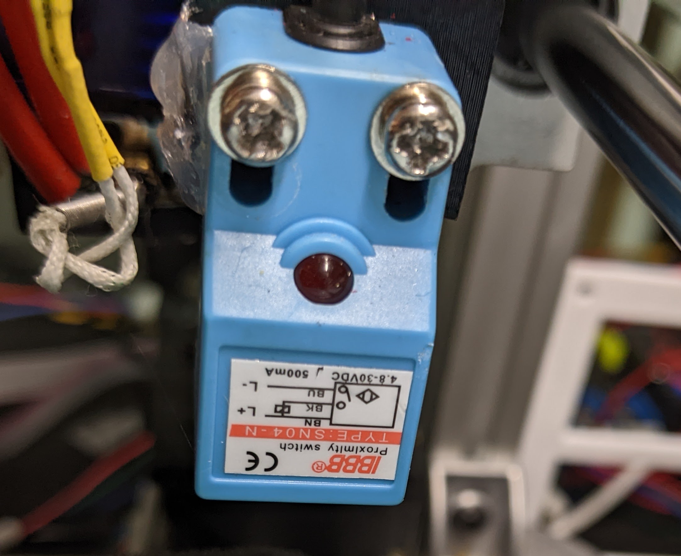
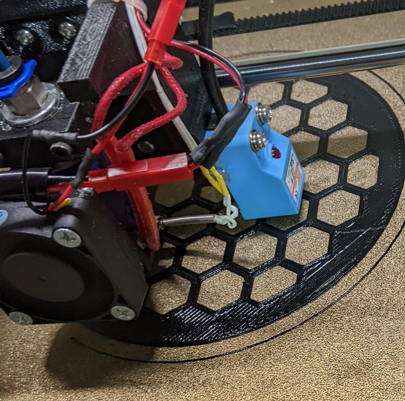
There are several ramifications to this editing that might not be obvious at first glance. For one, you can set up UBL with no Z probe at all. Sure, it is a pain, but you can manually measure all the points and the printer has provisions for helping you make that measurement. Ideally, though, you’ll have a Z probe of some sort. Inductive probes are popular as are BL-Touch and its many imitators. The photo shows a typical inductive sensor.
The other thing editing can do for you is to set points that your Z probe can’t reach. Most probes have some offset from the print head and can’t reach every point the print head can. For example, if the probe is 10 mm to the right of the head and the head can only go to 0 mm, then the probe can only measure X coordinates of 10 mm or greater.
It turns out, if your bed is pretty consistent, you may not have to measure these extra points, but you can if you need to. Marlin is pretty good at guessing the missing values and even if it is wrong, it might be easier to start with the guess and then make adjustments.
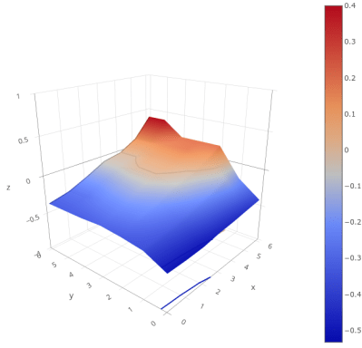
One interesting side effect is that once you have a mesh, there are a variety of ways to visualize what your bed looks like. Then you might want to adjust your bed to be flatter, but if you do you will have to rebuild your mesh. I’ll show you a few ways to get a plot like this next time.
Building UBL
You should already know how to build Marlin for your machine. If not, you’ll have to start there. Once you can get Marlin to build normally, you’ll need to deal with these configuration parameters:
In configuration.h (with some added comments for clarity):
#define AUTO_BED_LEVELING_UBL  // and turn off or remove other AUTO_BED_LEVELING_* defines
#define RESTORE_LEVELING_AFTER_G28 // pick one of these if you want Home to restore level or turn it on
//#define ENABLE_LEVELING_AFTER_G28

//#define PREHEAT_BEFORE_LEVELING // you can enable this section or just preheat manually
#if ENABLED(PREHEAT_BEFORE_LEVELING)
#define LEVELING_NOZZLE_TEMP 120 // (°C) Only applies to E0 at this time
#define LEVELING_BED_TEMP 50
#endif

#define MANUAL_PROBE_START_Z 0.2 // Manual probes will start here so if this value is large, you will waste a lot of time

#define ENABLE_LEVELING_FADE_HEIGHT // When to fade leveling effect to zero (10mm is good)
#if ENABLED(ENABLE_LEVELING_FADE_HEIGHT)
#define DEFAULT_LEVELING_FADE_HEIGHT 10.0 // (mm) Default fade height.
#endif

#define SEGMENT_LEVELED_MOVES // split moves into small pieces instead of entire grid
#define LEVELED_SEGMENT_LENGTH 5.0
// This section sets the parameters for the mesh validation pattern if you want to use it
#define G26_MESH_VALIDATION
#if ENABLED(G26_MESH_VALIDATION)
#define MESH_TEST_NOZZLE_SIZE 0.4 // (mm) Diameter of primary nozzle.
#define MESH_TEST_LAYER_HEIGHT 0.2 // (mm) Default layer height for G26.
#define MESH_TEST_HOTEND_TEMP 205 // (°C) Default nozzle temperature for G26.
#define MESH_TEST_BED_TEMP 60 // (°C) Default bed temperature for G26.
#define G26_XY_FEEDRATE 20 // (mm/s) Feedrate for G26 XY moves.
#define G26_XY_FEEDRATE_TRAVEL 100 // (mm/s) Feedrate for G26 XY travel moves.
#define G26_RETRACT_MULTIPLIER 1.0 // G26 Q (retraction) used by default between mesh test elements.
#endif

#elif ENABLED(AUTO_BED_LEVELING_UBL)  // settings for UBL
//#define MESH_EDIT_GFX_OVERLAY // Display a graphics overlay while editing the mesh
#define MESH_INSET 0 // Set Mesh bounds as an inset region of the bed -- to avoid clips or other margins
// Set the # of rows/columns to use
#define GRID_MAX_POINTS_X 7 // Don't use more than 15 points per axis, implementation limited.
#define GRID_MAX_POINTS_Y GRID_MAX_POINTS_X
//#define UBL_HILBERT_CURVE // Use Hilbert distribution for less travel when probing multiple points
#define UBL_MESH_EDIT_MOVES_Z // If you turn this off, the nozzle could scrape the bed while moving between edit points
#define UBL_SAVE_ACTIVE_ON_M500 // Save the currently active mesh in the current slot on M500
//#define UBL_Z_RAISE_WHEN_OFF_MESH 2.5 // You can force a height when there is no data for a point

#define UBL_MESH_WIZARD // add a wizard for setup to the menu

// more menu setup
#define LCD_BED_LEVELING
#if ENABLED(LCD_BED_LEVELING)
#define MESH_EDIT_Z_STEP 0.025 // (mm) Step size while manually probing Z axis.
#define LCD_PROBE_Z_RANGE 4 // (mm) Z Range centered on Z_MIN_POS for LCD Z adjustment
#define MESH_EDIT_MENU // Add a menu to edit mesh points
#endif

// What do do after a Z probe
#define Z_PROBE_END_SCRIPT "G1 Z10 F12000\nG1 X15 Y200\nG1 Z10"
There are also a few settings in configuration_adv.h if you need to override, for example, the three-point probe corners and things like that. You can usually leave these alone. If you have an 8-bit controller, you may not have enough memory to build UBL. There are a few ways to reduce the memory footprint, but not by much. Better to upgrade to a larger board.
Next Time
Once you have the firmware built and downloaded to your printer, you are ready to go, right? Not exactly. Even though the printer now knows about UBL, you have to set it up which involves setting a Z height and measuring your first mesh. I’ll show you how that works next time.


Isn’t this exactly what the Prusa MK3/S/+ does? Right down to storing the meshes for different surfaces?
Yeah. It’s stunningly mindboggling for me. From similar or outright exactly same origins i.e. Reprap two completely different worlds developed.
Next time the world of chinessium will discover XY(Z) angle calibration&compensation with dedicated calibration points on bed.
Here I must mention a discussion with my colleague at the end of 2016: He was happily and passionately talking about how he bought a 3D printer from Aliexpress for less than 5000Kc (less then 200eur) and how after *several* days he finally manged to calibrate it. And I with my Prusa MK2 absolutely didn’t understand. It took me minutes and lot of questions to understand that it does not have any induction probe and dedicated calibration points or any other way to measure axes skew (like all-axes mechanical sensing probe) (and with that cheap frame it absolutely was not orthogonal and needed fixing or compensation)….
And after 5 years most of the chinessium or even proprietary BS printers do not have skew calibration.
I started with a Wanhowever you spell it. The one that Aldi was selling, but I didn’t get it there. It worked OK, but had some issues. I ALWAYS struggled to get the first layer right. It finally just stopped working, so I bit the bullet and paid the money for an MK3. I’m a Prusa Fan Boy now. It would take a lot for me to give up my MK3S+, and I really want to see the MK4 (if they ever do one) and the upgrade kit for it.
I chose a MK3S as my first printer and totally love it, because it puts out super consistent prints. First layer adhesion problems? Newhere to be seen! But, it costs as much as 4 to 5 Ender 3, so I can understand that people buy other printers.
I bought an E3 Pro lately (as a simple second printer when the MK3S is running) and you have to know how to check every angle and tune the gantry to make it print well. Out of the box that thing would not work properly!
The MK3S(+) has a major design flaw anyway, from a engineering point of view: Changing the linear bearings to re-grease or change them forces you to completely take apart. Proper! adjusting tension on the belts after assembly still isn’t possible without modification…
Yeah, needing to disassemble the MK3S to re-grease the linear bearings is pretty annoying. Prusa tells you to wipe lube on the smooth rods, but the wipers on the linear bearings prevent grease on the rods from actually getting to the bearings.
While true that you would need to disassemble the whole printer to get lubricant inside the bearings, that’s not a scenario that should ever come up during normal operation. The Prusa maintenance guide is pretty clear about wiping down the rods to keep dust from accumulating, and letting the lubricant that’s already inside the bearings do its job.
I think there’s some confusion here because on the Prusa Mini, they are using cheaper linear bearings as a cost cutting measure, and it’s recommended to initially lubricate those manually. But this shouldn’t be necessary on the MK3’s bearings.
Of course, you’ll find people claiming that the lubricant on the MK3 bearings isn’t good enough, and that you should flush them with IPA and pack them with white lithium. But frankly, there’s always a subset of 3D printer owners who are obsessed with these sort of “mods” they believe are going to help them squeeze some more performance out of their machine; regardless of whether or not they have actual evidence to show there’s an improvement.
So until Prusa updates their official documentation, I’ll trust the folks that have to date cranked out more than 100,000 of these things to very happy customers, and leave the bearings as they are.
Tom: Prusa does say that you should disassemble the printer to grease the bearings:
> Bearings: Clean and lubricate the bearings and rods as shown this guide. Despite cleaning and lubricating the smooth rods, it can happen that the axes’ movement is still not smooth. In this case, please remove the bearings from the printer and lubricate them from the inside with a pea-sized amount of lubricant.
https://help.prusa3d.com/en/article/i3-printers-regular-maintenance_2072/
But, I think Prusa’s instructions aren’t good (or, are a compromise to simplify the assembly) – as has been noted in discussions around greasing the bearings, the bearings are shipped in a light protective oil which will wear off after some months of operation. The instructions for linear bearings (e.g. the LM8YY from Misumi) instruct that they must be lubricated before use. There are people who have reported their linear bearings cutting splines of their smooth rods.
I agree that there is snake oil in the 3D printing world, but I don’t think that this- following standard practices for the linear bearings- is it.
I think I’m an example of why Prusa doesn’t recommend lubing the bearings – I stripped the shipping oil with isopropyl, then put PTFE grease in the bearings. But, I didn’t properly pack them by applying pressure with the smooth rods, I just ran the lube through the bearings. My y-axis was loud. After a while, I took apart the y-axis and properly packed the bearings. Now, it’s much quieter.
I have an Ender 3 with Jyers’s Marlin fork (highly recommended). I use 3×3 bed leveling at every print start simply because I sometimes remove and clean my glass plate (some prints need UHU glue stick handling it) or I turn it 90 degrees to shift the usage pattern. I still have the spring loaded bed holding mechanism, so assume it would be randomly off of the 1/10 mm accuracy.
Cheap pro tip: Use some beeps
M300 S4698.63 P250
M300 S5274.04 P250
M300 S4698.63 P250
to indicate printing end.
I use Jyers on my V2 and use the 10×10 pattern but have it for a 2×2 tilt mesh probe before every print. I only redo the entire mesh if I’m changing build surfaces
Note that glass isn’t flat. An UM2 bed (~200x200mm) on average has a 0.1mm “non flatness” (deviation from a flat plane) and worst case we’ve seen 0.2mm.
Also, as your glass plate is heating up, it deforms. And even after reaching your final temperature it takes 30 minutes before it no longer changes shape. You can check this by just repeating the measurements for an hour while heating up the bed.
Which is why a first layer of 0.3 or thicker is quite important, it works around this non-flatness issue quite well.
(Former Ultimaker employee, and creator of Cura)
Or use a print bed better than a warping glass plate. These cheap printers have limitations that are due to their materials and design (glass beds, moving beds, loosening bed mounts, wobbly uprights, etc), and the sensor and software approach is appealing because it allows them to minimize those issues while remaining cheap machines. A better build with better materials and design would eliminate the need for the constant probing and adjusting.
I have a delta, for instance, that I’ve only calibrated twice in the past couple of years (when I changed hotends) and it prints perfectly every time, no probing, no adjusting. The downside is that I could have bought a half dozen Ender 3s for what it cost to build it.
You missed my point. It is not warping, as in, it is not permanently changing shape. Its shape depends on temperature.
And yes, a decent construction with a fixed bed almost never needs adjustments. I almost never adjust my Ultimaker (Origonal+)
But, if you print a lot, it helps to swap out buildplates to give a plate time to cool down while you start the print on the next one.
A lot of people think they need autoleveling to achieve reliable 1st layer adhesion so they use multiple motors and screws to lift the bed or X axis. As soon as you add multiple motors you have to use autoleveling because the motors jump every time you power them off.
I’m a fan of just using a flat plate (cast aluminum with a layer of PEI), setting it on a kinematic mount, and lifting it with a single motor. I use two belts to lift the bed with a 30:1 worm gear drive so the bed doesn’t drop when the power is cut. It never tilts so I don’t have to relevel the bed unless I take it apart- the last time was about 2 years ago. It doesn’t make for mesmerizing youtube videos but it just works, each and every time. Configuration is dead simple, and there are no extra motors, drivers, sensors, or cables to deal with.
Mrehorst, this is the way. I wish more printer designers were familiar with your work. I’m a huge fan.
https://hackaday.io/project/163632-kinematic-mount-for-3d-printer-bed-moving-in-y
He also has a blog that covers more aspects of his printer.
Sounds nice. I’d be very interested in the way you did your kinematic mount. Are there any pics or drawings of it?
Cheers, Jan
I found UBL documentation was fairly straightforward. The biggest problem is the same one everyone’s always been fighting; manufacturers are too dumb to enable it in the firmware package they deploy. Heck, they don’t even bother with basic manual mesh leveling systems half the time.
I use and tested many inductive sensors on my delta and there are some gotcha’s that aren’t addressed. A major one is the frequency response of sensors are typically 500Hz on sensors until you hit the $60-80 MSRP range, then it’ll be 1KHz and as you continue to increase your price you can hit about 3KHz outside of very specialized sensors. This means your probe speed for repeatedly measuring a distance plays a major part in your overall precision. I ended up using an 8mm dia. 1KHz k1 (all metal) sensor i could get for about $30 on ebay that’d normally be like an $85 part direct. Another big gotcha is the spec. on trigger range typically varies 10% of the target distance of the sensor and for some sensors that still occurs while other variables such as temperature are stable. They industrial design function of many inductive sensors is for counting teeth on a wheel, passing objects, or maybe a contact free endstop for which all of these behaviors are acceptable, while not so much for 3d printer components.
I mentioned endstops before and I’ll throw it out there again, the most repeatable mechanical endstop I tested were some sanwa arcade button switches. I haven’t tested mechanical keyboard switches but i suspect some quality ones would also do MUCH better than typical industrial switches on the sub mm repeatability.
A NAMUR Inductive Proximity Sensor may be the way to go. By misusing them slightly, they can function as an analog sensor. We used many Turck Bi5 sensors this way, measuring displacements in the range of roughly 2 to 5 mm with .025 mm resolution at 1 kHz sample rate. Not cheap but very reliable. Measure the voltage across the sensor with the positive lead pulled up to 5 or 12 volts, the other lead pulled to ground. Experiment with different pull up resistors to find what works. A few op amps to low-pass filter, amplify and offset the signal allowed very nice readings.
RRF here so no rebuild Marlin, sort of wish I had a Marlin machine to play with building firmwares and such. But not on my printer that I use all the time. My printer is not fancy just a E3 but I installed a BTT E3 RRF board, the convenience of DWC is just to good.
How has it been as far as wireless and print quality?
I have two of them with the two driver add-on board but haven’t had time to do anything with them yet. I was the first person outside testers to receive the board since I won one before it was released and ordered the other as a backup, I also have an SKR Pro and a bunch of tmc5160 driver’s for another project I haven’t had time to build either.
I don’t have an ender so it’s not drop in but it will still fit with a custom mount
I’ve had a Prusa through a few generations with its clever scanning and bed compensation and it was a game changer from older machines. However the coolest I’ve experienced is how my Creality 6 Max does it. While not a flawless machine, the whole hot end is mounted to a load cell (think kitchen scales). This means the probe is the hotend itself.
Has anyone thought of using a dvd lens module to make an auto-calibrating distance measuring device to actively control the z mapping height? It may work as is… or may need a led laser pointer to make it safer to use instead of the dvd laser itself?
This seems to me like it could work? Can a better brain then mine grow this idea seedling grow and see if it is possible? Would love to discuss more if anyone cares to give it a spin?