[Hans Summers] runs a site qrp-labs.com, selling self-assembly kits mostly for radio gear and GPS applications, and had some production problems with his QCX-mini QRP transceiver kit. They were using an assembly house that had some problems with a sub-contractor going under during the pandemic, and the replacement service was somewhat below the expected level of quality, resulting in a significant number of SMT populated boards coming out non-functional. Obviously, not wanting to pass these on to customers as a debug problem, they set to work on an in-house QA test jig, to give them the confidence to ship kits again. The resulting functional test jig, (video, embedded below) takes a fairly interesting approach. Skip the video to 9:00 for the description of the test jig and detailed test descriptions.
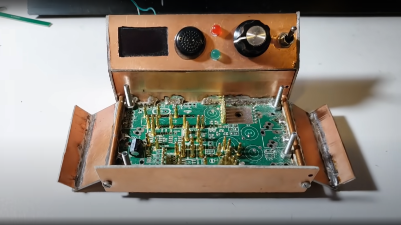
By taking an existing known-good PCB, stripping off all the SMT parts, and moving the through hole components to the rear PCB side, pogo pins could be soldered to strategic locations. Building the assembly into a rudimentary enclosure made from sawn-up raw copper clad board, with the pogos facing upwards, and a simple clamp on top, allowed the PCB-under-test (let’s call it the UUT from hereon) to be located and clamped in place. This compressed the pogos in order to make a firm electrical contact. A piece of MDF that had been attacked with a dremel did duty as a pressure plate, with cutouts around the SMT component areas to achieve the required uniform board pressure and keeping the force away from the delicate soldered parts. All this means that with an UUT connected via pogo pins to a through-hole only test PCB, the full circuit would be completed, if and only if the UUT was completely functional, and that means defect-free soldering and defect-free components.
Next the firmware was rewritten to do duty as the test controller, which when powered up would step through a sequence of test scenarios and measurements, logging the results to an OLED display and a serial interface. This rig survived 1,000 SMT tests without failing, giving [Hans] the confidence to ship out new kits and providing a database of datalog results as a backup should a customer have an issue during final assembly. All-in-all a smart idea to solve a difficult problem, with nary a custom test jig PCB in sight!
These pages have been graced with many a pogo-based test rig over the years. Here’s one to start, and if you’ve got a handy laser cutter and some scrap wood, making an accurate test rig is no bother either.
Thanks [Paul] for the tip!


Wow, I know that hacker
Minor correction: it wasn’t my QCX+ that had the SMD problem. It was the QCX-mini http://qrp-labs.com/qcxmini
FYI the test jig is still going strong almost a year after construction and has now tested something like 2,500 boards. The PCBA production problems were solved but we still run the test jig on every board to make 100% sure before shipping to customers. There’s a very low failure rate now (production yield is never 100.00%). And I like the concept so much that I have built several more test jigs for subsequently designed products and committed myself to doing this on all future products too. As a final layer of quality control it’s really useful.
Ah OK, minor slip. I can see it is obviously the smaller PCB. Corrected.
we suggest use Cnomax Pogo Pin,Quality is better guaranteed for PCB test
BTDT… These round-head pogo pins are not the ones you want… Put a reworked PCB with some flux residue on there and they get pretty unreliable until you clean everything with eg. acetone…
Use some spear tipped once and/or use test pads with some holes. The eevblog forum has nice writeups on this topic.
I make these jigs by simply modifying the kicad files.
First, remove everything but the test points in kicad.
Then replace the location of the footprints (front to back and vice versa) and replace the footprint to something which can take your pogo pins) in a text editor.
You may also want to move your outline to the right silk screen layer.
Go back into kicad and add some pin headers to break out everything and add a new, bigger outline.
Registration can be done with precision pins.. they are pretty cheap… 2.85mm is fine for a 3mm hole.
These are also very usable to align the solder past stencil… Just add the holes to the mask layer. You then get the holes on the stencil as well
I use just 1 at one corner and have the opposite corner “swing” against some stop block.
Usually I integrate this into the 3d printer mechanism holding everything down.
Maybe I’ll do a complete writeup some time.. anyways, just don’t use these round head pogo pins.
73
Hi Johann
Thanks for the advice and I know you are technically correct, but there were a number of constraints.
Firstly the target board (UUT) wasn’t designed for connecting test points. 2,000 boards had already been made there wasn’t an opportunity to redesign. Since it’s quite a hybrid of SMD (both sides) and through-hole (for various reasons including performance and avoiding microphonic effects), there were a large number of required connections between the jig and the UUT – if I recall I used around 55 pogo pins. The round head ones were perfect for the application due to the fact that each round head makes contact at a through-hole component position, being a round hole that leads to a relatively large contact area. In practice we didn’t have any issues with poor connections in the over 2500 units tested so far.
The second critical constraint was time! The product was in great demand, there were a lot of waiting customers. There were 2,000 already-manufactured boards to test. It was ideal for me to use a production board as the template for holding the Pogo pins because everything was already lined up in the correct positions. Ordering fabricated PCBs takes around 2 weeks in my case and there wasn’t time to wait 2 weeks. A dollar-store hot air gun and a few minutes of fire was all it took to remove all the SMDs. A hack, but quick :-)
Finally, and again related to the time constraints, I had to limit myself to the Pogo pins available here in Turkey where I live. I got them delivered 2 days after ordering online. I certainly couldn’t wait weeks for post from China.
So it was all about throwing something together fast in sub-optimum conditions and parts availability. A hack! In the end I’m pretty pleased with the way it all turned out. It has proven robust and reliable over almost a year of operation and 2500+ units tested. It solved all our problems of customers getting defective units. The 21 tests are such that on the few that fail, it gives enough diagnostic information on the OLED to pinpoint the fault.
Never mind my comments…
My guess is that the edge of the THT hole made it work reliably since the hole has a sharp edge which cuts through any residues.
I tend to have smd pads only due to space constraints. Here, any “dirt” will stick to the round head and you’ll get unreliable contact for the following boards…
Usually, I order some 2sided jigs with every PCB where I need to test/programm more than maybe 20… It took me a while to recognize why the jigs failed after a while for no reason.
I usually Order from JLC 95% assembled PCBs. Most of the time a TCXO and/or some connector is missing. So there will be some flux around and the tiniest amount can ruin your day. I’ll need to figure out a better but still economic washing solution at some point…
But it’s good to know you got thousands of board through those cheap contacts… I was worrying how long they would last since I now have a product which should sell in the hundreds per year (I tend to do niche products)
Btw, if you shop around amazon, you find pogo pins with around .6 and 1.1mm diameter. So they perfectly fit common THT holes.
Having maybe 1 or 2 empty PCBs below as a spacer/alignment tool, and soldering them from above makes the alignment (ie having them 90°) extremely easy… Again, no problem if you have big pads, but handy to know :)
Vy 73
Wow…brilliant one, Hans
I have been using Pogo pin test jigs based on the production PCB for about 15 years.
http://www.w9xt.com/page_electronic_projects_test_fixture.html
Mine are quite simple compared to the one Hans built. I really like how he used PCB material to build the case and especially the clamp. Well done!
Nice to see Hans himself weigh in here. I don’t know how he keeps up with the social media and email traffic like he does. Plus design the hardware, write the software, run a great business, and have a family. He must not sleep.
My QCX-mini was one of that first batch with a bad op-amp. Easy enough to fix, but I’m very glad the next one I get (for 20m) will be tested with this jig.
I’m waiting for that next batch of QDXs to be available before I place my order though :-)
I confess I did not even try to get the first batch of the QDX because a) After the QCX-mini glitch I kind of expected a minor cleanup rev on the next version. and b) I didn’t want to participate in the pileup. It turns out all 400+ sold out in something like 14 minutes anyway.
Hi Paul
Oh man, the skeep really caught up with me last night. The family were away. With nothing to end my night, I finally only woke up at 11:30am!
You missed the second batch QDX. They sold out even faster in 4 mins 44 seconds!
I’m working on the 3rd batch now which will be a much larger number (2000 or 3000) but fighting the global semiconductor shortage is a whole other story.
73!
Hmmph. I missed the announcement. I can’t keep up with the traffic in the QRP-labs group. I’ll have to set up a script or alert.
Wow, that’s pretty clever. Took me a minute to figure out what it was doing from the article (testing a partially assembled board by completing it thru a board with only the missing parts assembled) but I was glad I stuck with it, that’s a great trick to know.
I used to do this all the time. before we started outsourcing fixtures we would use phenolic board/SLA prints/original circuit board to build test fixtures. towards the end of my fixturing days we moved to outsource fixtures with clamps and a super expensive test base with swappable fixtures. Used national instruments and LabView to automate the whole thing. I miss doing that work. I should really try and do more consulting on this stuff, as it was super fun to design and write automation code for these functional tests.
I didn’t watch the whole video but we would always run a power shorts test first. supply 5vdc (or what ever power rail you are testing) through a resistor that matched the boards internal resistance to ground and check if we got 5vdc or ground. then we would power up the board. this was way faster then doing a resistance check as most boards had caps and that would never be the same each time.