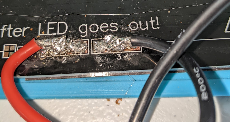
There’s an old saying about something being a “drop in the ocean.” That’s how I felt faced with the prospect of replacing a 12 V heated bed on my printer with a new 24 V one. The old bed had a nice connector assembled from the factory, although I had replaced the cable long ago due to heating issues with that particular printer. The new bed, however, just had bare copper pads.
I’m no soldering novice: I made my first solder joint sometime in the early 1970s. So I felt up to the challenge, but I also knew I wouldn’t be able to use my usual Edsyn iron for a job like this. Since the heated bed is essentially a giant heatsink for these pads, I knew it would require the big guns. I dug out my old — and I mean super old — Weller 140 W soldering gun. Surely, that would do the trick, right?
Well, the Weller…
Obviously, it didn’t, or you wouldn’t be reading this right now. It could be it just needed a new tip — the thing is seriously old, but it just wouldn’t get the pads hot enough for solder to truly flow. I did finally get the wires to stick, but the solder joints were so bad I could not imagine they would hold up to constant flexing.
I thought about trying a hot air gun, but I decided I’d try something even different: flame. You can get butane soldering irons and torches from a variety of places at many different price points. Being cheap, I picked up a Schneider-branded iron from Harbor Freight. The handle has three attachments that nest. One collar just shoots flame like a torch. A little tube that fits the collar keeps the flame away and you get hot air out the end. That tube can also take a soldering iron tip.
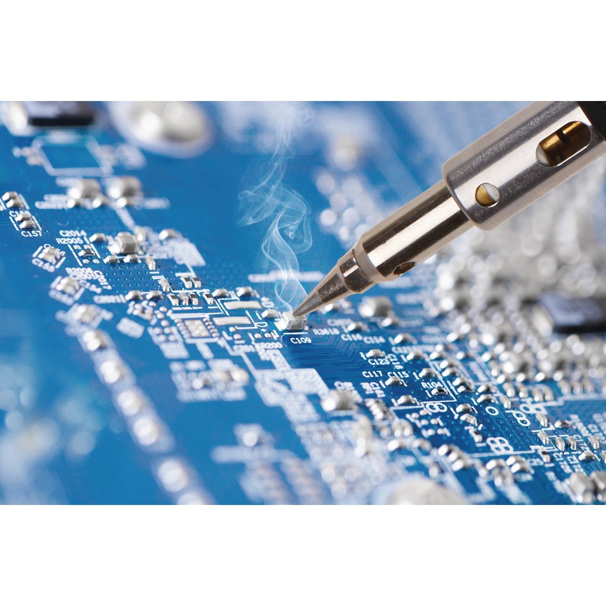
We think the promotional picture on the Harbor Freight website (see adjacent) might be a bit optimistic. We don’t recommend this iron for doing surface mount work on a PCB. However, I needed a lot of heat and, as the video below discusses, the thing puts out almost too much flame. You can mod it like [marshkid1] does in the video to make it put out less, but that wasn’t my problem.
Turns out, it isn’t as easy to get butane as it used to be. Besides that, you really want butane made for this sort of tool so it doesn’t clog. I settled on just using lighter refill butane and took my chances. So far, so good.
There was only one problem. Despite the vigorous flame, the solder just wouldn’t really melt enough to flow. The tinning on the wire would melt and a little of the top surface of the pads, but with the entire surface area of the PCB resistance to sink heat, it was impossible to get a good joint.
What to Do?
I contemplated heating the whole board up in an oven or with a hot plate. I even thought about soldering under an IR lamp. In the end, I used a two-pronged approach. I removed the soldering tip from the iron and let it jet hot gas over the connections. Then I used the Weller and I did finally get reasonably good solder flow. The hot air alone, however, was not sufficient.
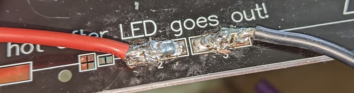
The joints aren’t the best-looking ones I’ve ever done, but it seems to be holding even under use. Of course, I soaked everything with rosin, tinned everything, and made sure everything was clean. There was just too much heat capacity.
I may yet try again, even though it is working well enough for now. Maybe I need one of those huge automotive soldering irons. Or maybe I should use the SMD heat gun to preheat the joints. I’m sure I’ll get some things to try in the comments.
I don’t think this is the answer. Maybe it takes a PCB heater to solder a PCB heater?


I let my RadioShack soldering iron heat all the way up then hit the iron with a torch to bring it to a probably irresponsibly high temp and soldered it easily enough. I was removing the connector on the aner a3 bed that’s prone to failure
Try using a fireproof “blanket” of some sort (wall insulation material?) to cover the exposed copper
This is one of those moments when leaded solder is your friend. That and your trusty Weller soldering guns. Usually pick one up at a local hamfests for 5 to10 dollars. If you really need more heat, a stained glass soldering iron can crank out some heat
I almost exclusively use leaded solder…
and?
It’s been a while since I’ve met a member of the Holy Church of Lead Poisoning!
A sensible alternative is Bismuth-Tin eutectic solder. 140 degrees melting point.
Suggest 3 stage soldering with the hottest electric iron you can find (to channel the heat to the point of contact rather than all over the place, particularly with PC boards etc.) – I a 200W Mikayo for under $30 on Amazon. You don’t need these often unless you do stained glass work but they’re ridiculously handy when you do.
First saturate the wire with solder and let it cool then – separately – create a nice pool of solder on the bare connector surface and let that cool. These can be solidified when you push them together and apply heat. That eliminates the need to apply sufficient heat to very different materials all at once – you’re just fusing the solder at the interface at that point which gives a much higher probability of success since the flow into the wire and onto the pad surface has already been done.
This alone usually works well for me on tough solder joints. Also, tossing your new heated bed on your old heated bed and cranking it to 95c to saturate it wouldn’t hurt.
Is that Harbor Freight iron not catalytic (like a Weller Portasol) and just uses a flame behind the tip? If so, I can hardly see it working well.
The best way to deal with this kind of thing is my favorite soldering tip on my favorite soldering iron: a Metcal (coax style, not bipin) with a STTC-836P tip — at least, I think that’s the one. Big chisel, highest temp. Fantastic for big milspec connectors, general desoldering, stuff on huge ground planes, etc. Trick is getting a secondhand Metcal setup on eBay. Once you start using a Metcal you can never go back haha…
I don’t think it is catalytic, but it does work nice as a hot air gun.
Yeh, have had both types, and the not-catalytic ones seem to be only good for when you want a open flame.
If its similar to the one HF had 10 years ago pretty sure it is catalytic as there is a small ceramic matrix that glows red
the most appropriate approach seems to be the hot plate pre-heating + beefy soldering Iron imho
A hotplate (very simple one, just something you could by at a camping store) is what we used at Ultimaker to make prototypes beds, worked really well.
+1
Definitely easier if the pcb is preheated to an elevated temperature, and the iron is just bumping it over the melting point. Helpful to sit the pcb on a aluminum plate, which is sitting on the electric hotplate.
Try using a big piece of copper (like a small hammer) with not too pointy end (the more thermal mass near your soldering point the better) and heat it with flame until it’s almost red hot. It should have enough heat capacity to melt that tin. But – it can also weld itself to your heated bed and ruin it permanently if you are not careful and leave it too long near pad. Otherwise – check out some really big soldering iron for soldering roof water troughs. But they use iron tips, best tip is the one which has better heat conduction properties than your soldered material. With aluminium that means only a big chunk of copper will be enough.
soldering “coppers” work great after they have been tinned,
get your chunk of copper hot and rub it on tin as in the element until it gets a shiny tin colour,unless you do this the solder wont flow right.I have used these and they work great.
Hot air plus soldering iron. The hot air can keep the copper hot (doesn’t have to be solder-melting hot), then the soldering iron can focus on the joint, bringing just that area the rest of the way to soldering temp.
That’s essentially what I did. Seems to be OK.
^ this, a heat gun, hot air station, or hotplate (even just an electric stove top) means the soldering iron only has to get the solder over the hump to melting point.
Also, PortaSol gas irons are the daddies and well worth keeping in the toolbox, the open flame is something like 1500C.
I think the hot plate ($15) idea along with a good soldering iron would probably be the best bet.
Get a hot plate if you can, if not, get a clothes iron. Dial it up to 150C or whatever temperature is safe for your bed. Put your bed on it and wait for it to equilibrate thermally. Then solder with a regular soldering iron. This way there will be much less delta T between the bed and the iron tip and much less heat flow to the bed, so your solder won’t instantly solidify on contact.
You could do a TIG weld with low current instead of soldering. I’m not 100% sure but probably 5-10 amps would do.
I’ve done some tig brazing this way. The problem I see is that often the high frequency start will damage the material through electrical erosion. Maybe if you set it up for DCEP you wouldn’t crater the workpiece.
Every so often at hamfests or antique stores I will see these really huge old soldering irons. Typically they look more or less like a typical modern iron only 2 or 3 times as large, a wooden handle, braided cloth covered power cord (I hope it isn’t asbestos) and no markings such as make/model/wattage.
At the hamfests they usually only go for a dollar or two but antique stores.. well.. everything is marked up as if it was collectable.
Anyway, I bought one at a hamfest a long time ago and it is great for this kind of job. I used mine for my own heated bed. It was one of those 12/24 dual voltage ones where you have to short a couple pads for 12V. I layed a metal strip across the two pads to be shorted that I saved from a pack of DuPont pins, you know.. the strip that they come attached to.
All that heat-sinking metal was no problem. It heated and wetted as easily as a typical IC pad with a normal iron. I also use it for PL-259 connectors, fat grounding tabs and things like that. I think I paid $1 if I remember right.
I don’t have a picture here and like I said, they usually have no markings but here’s a pic of something similar though I might hold out for a safer looking power cord. https://www.collectorsweekly.com/stories/233403-vintage-electric-soldering-iron
I have one of those. The cord is in rough shape, the handle has a massive split, and the tip is held into the body with a 5/16″ bolt about 2″ long sticking out the side so I only use it when I’m desperate and near a fire extinguisher. I probably need to do a semi-restoration on it some day.
This article set me to looking for the massive copper “irons” we used to use when soldering flashings and roof jacks and other water resistant sheet metal parts in a previous life. I found pictures, but all were curiously labeled as “vintage”, “old” and the like. It’s as if someone is trying to tell me something…
I bought at a 2nd hand store ($0.50) one of those big soldering irons that was made to rest on a kerosene torch a century ago. As a joke I left it on n the bench of our SMD soldering instructor when he wasn’t around.
He didn’t know what it was and got upset that someone had left “that piece of junk” on his bench.
I used a one-of-those to repair the armature wire on a Chevy starter motor once. It was big wire, 6 or 8 AWG, doubled over on itself, and my 150 Watt soldering gun wasn’t even beginning to get things hot.
It was just as you described. Wooden handle, cloth insulation, and big.
This ancient soldering iron made short work of the connection. I was able to get the joint fully-wetted and proper, and the results lasted longer than the rest of the car did.
10/10. Wish I still had access to that iron.
Should be able to do that with the big tip on TS100. Looks like you need better flux and use good lead solder like Kester 44 63/37.
A few years ago, I also had to solder new leads to the heatbed of my Anet A8.
Laid the bed on my glass-top kitchen range, heated it to the “can’t quite keep my finger on it” point and then soldered the leads with my normal Weller station.
Yeah, I made the mistake of trying to resolder the leads “in place” while it was still attached to my big-hunk-of-aluminum bed as part of a 12V to 24V conversion. Of course I’d taken the trouble when I originally installed the PCB heater both to (a) ensure it had good thermal conductivity with the metal bed, and (b) secure it with enough high temp adhesive to make removing it a nightmare. Huge amount of heat sink capacity fighting my attempts to fix the leads.
I basically gave up and am waiting for a new 24V heat pad to arrive, which will force me to peel the existing heat bed off. But by then if I damage it in the process no big deal because I’ll have its replacement handy.
I might be out of my element here, but maybe it would be possible to find a pair of traces/different pads and connect the supply with something like crocodile snaps? Then the board could heat itself, while the pads are being worked on…
I thought exactly the same. Especially that at some point wires were fixed to pads so for a short time maybe some current coudl’ve been applied
Wouldn’t it make more sense to drill the PCB and bolt the wires down?
This.
Too High of a risk that mechanical failure of the connection (increasing resistance) could cause fire.
It can be done safely but to do so is not really in the skill-set of the average 3D printer user and would require a redesign of the heater.
The top of the board needs to be flat (or at least be free of protrusions) when it is all said and done.
One could countersink the holes and use flathead screws, but the board is rather thin and that would not leave much — if any — meat for the fasteners to work with.
Add repeated thermal cycling (at least one cycle per print), and a moving bed (perhaps thousands of reciprocating cycles per print), and it’s a recipe for a bad time.
Solder isn’t perfect, and indeed is fairly terrible in many ways, but it does seem to work well for this particular application.
Thousands of movement cycles shouldn’t be an issue for bolts. I’m not convinced that the heating cycles are either.
But if the top needs to be flat that’s an issue, and if the board isn’t solid enough to drill obviously that’s a no-go. Seems like a redesign to have the wires attach to the bottom might help? Or an extended area to one side where the wires can attach out of the working area? (I’m assuming the need to be flat is to avoid collisions within the printer’s working area)
I mean, bolts keep my car together, and they go through thousands of movement cycles a minute, plus a heating cycle every time the engine warms up.
Wouldn’t pre-heating the bed in a oven be the most obvious solution? And have helping hands holding the wires in place when it cools down?
Or use a hot plate like for reflow or even an electric hob, that should work pretty well.
Al just to say I do enjoy your first-person practical columns, they stand out among all the here’s-someone-doing-something-crazy-on-youtube articles, thank you.
The big Weller guns demand that the electrical junctions be sparkling clean to get maximum heat at the tip. It is basically a high-current low-voltage transformer with the secondary winding being a single or twin loop of metal and the tip being the completion of that circuit. You’re basically heating a low-value resistor. If the tip-retaining nuts (better design) or screws (Weller’s cheap-out redesign that never worked well) are not super tight and the copper from the tip shiny where it makes contact, you will lose a lot of current (= heat) at those junctures rather than at the tip where you want it. It really doesn’t take a lot of extra resistance to reduce the tip output to the equivalent of a 15-Watt iron.
More than a handful of decades ago, we had these in our high school electronics shop class. Tip nuts rarely lasted a month; soldering iron cords got down to 12-inches due to multiple repairs for melted insulation because people would just toss them on the bench.
He said get the big guns out. To me that means Weller’s 240 watt big gun not the standard size gun mentioned. How anyone manages to do stuff bigger than surface mount with a pencil type iron is a mystery to me. I have a gun in a holster hanging under the bench top at work and home. Tips for those are simple and very cheap. 10 gauge solid wire. You’re only 4 seconds away from action on any work.
I routinely do thru hole boards as well and get into tube powered stuff with a gun and a trigger finger that modulates the heat. Typical big terminals TO220 tabs etc. on boards didn’t get hot enough the first time through and get fixed on the quick, often the whole repair. Done!
Grab all of those vintage Weller guns, the new ones have screws to make the connections which at best fails and strips out if you keep it tight. The old ones have the hollow screws and right angle bend of the tip ends to make a righteous connection. Hundreds of amps have to flow here! Watch out for the usual China off brand versions, those screws are a tiny Allen thingy. The hex socket will fail even faster. Every month or so tighten the tip screws for maximum heating.
I just finished up a really big soldering job this weekend, and would have been tempted to use the exact same tools. That was my shower’s plumbing, and I used a propane torch.
Just use crocodile clamps to power the hot bed. When it goes around 100°C, remove the clamps and immediately solder it with your normal soldering iron. No need for hot air, oven, butane torch. Just use it how intended: hot.
That’s no PCB, it’s copper bonded to aluminium, which is one of the better materials for heat sinks. I have the same heated bed and could solder it without much problem.
Thoroughly clean the pad with alcohol 96% or higher.
A preheater to heat the bed or a couple of clamps to power the bed directly until it reaches about 150 degrees should be enough to solder wire on it.
Don’t forget to heat up the wire too, as thick copper wire sucks up and transport heat even better than aluminium.
Lastly you want to use a soldering iron with a large thick (ie 4-6mm) non tapering end, chisel with a stubby end should be fine. The more mass the better. Make sure to put the iron so that the largest area makes contact with the pad. 90W+ soldering iron would be great since it can supply the heat to upkeep the temperature at around 360 degrees C, beyond that you could burn the adhesive off the plate and burn the flux instead of allowing it to help solder it. Flux evaporates so you need to time it correctly or the flux just burns up or evaporates.
Flux is needed to avoid oxidizing the solder. When solder is hot it will oxidize a lot quicker and you get that crusty mess you see in the pictures.
I’m not sure rosin will help much in this case, maybe flux for smd, that beige cream like stuff from a syringe is probably better, it may stand the heat better.
Pre tin the wire until saturated. Once the bed is heated, pre tin the pad liberally. Add flux to the pad.
In quick succession: heat up the wire with the soldering iron for a few seconds, keep touching the wire with the hot tip then touch the wire and soldering iron on the pre tinned pad for a few seconds, then move the iron on top of the wire for a few seconds, and add more tin (3rd hand comes in handy right about now) until tin flows around the wire giving it a shiny finish, moving around the iron a little is fine. Make sure not to move the wire while the tin is not yet solid. It may take longer due to the pre heater. Make sure you wear protection as the heat creeping up the wire may burn your fingers, but this could also be an indication that you’re taking too long. If you move too much when solidifying it’ll turn crusty and dull and you need to start over.
It should be done in 20 seconds tops starting from heating up the wire until letting it cool down.
Dremel some heat relief around thepad. Obviously they forgot those ;)
Either a Weller D650 200W/300W, or the smaller D550 200W/260W, would probably work. They deliver 1100°F on the high power setting, 900°F on low.
Even before reading the article my first thought was “I’d put it into the kitchen oven and preheat it to 450F before attempting to solder it”. I’ve also been soldering for over 50 years and I’m pretty good at soldering wires onto parts that often amount to heatsinks; but even at that I wouldn’t attempt the job described without a good heat soak first. And like other commenters here, I use SnPb solder almost exclusively – it just wets better and produces more reliable connections.
I wonder if another alternative might be to solder to a piece of thinish copper plate then spot weld (as one would a lithium battery pack) the other end of the plate to the board. A solid blob of high temp epoxy over the top to insulate and provide additional mechanical strength would then seal the deal.
Why not just use a pencil torch and solder it like plumbers do?
I had a similar topic some weeks ago. Soldering copper cable to a copper pipe. The solution is two fold:
– Flames (I used a camping torch)
– Plumbers soldering lead. It behaves much better with these high temps and sticks better to copper. The usual electronics lead gives the result pictured in the article.
Cons: The calbe insulation will melt an burn quickly.
How to heat up a heater….. hmmm…. I can’t think of any possible way…….
The solder gun is a good way of doing it however the tips on those guns suck. I typically ditch the tips and use 14 awg solid core copper wire. Heats up super quick too. When I replaced my heated bed I used a ton of flux, tinned the pads, tinned the wire, added more flux and soldered it on. Another trick I have heard about was using a skillet and put it upside down on a stove top with the plate on top then heat it to 200 – 220 then apply flux and then solder.
My old Weller 140W seems to like #12 instead. #14 tends to fall apart after a few uses, in my experience.
Just buy one of these “Lutownica transformatorowa ZDZ LT-125.Jesteśmy jedynym PRODUCENTEM.” https://zdz-lodz.pl/lutownica-transformatorowa-125-p-28.html , and you will never need anything more (assuming you will never go for soldering way over 10mm^2 flexible cables). You need help just contact me. (I’m not connected to this company in any way, just have been using one 75W and been able to solder almost anything up to 6mm^2 without ever thinking about it)
Bad design they didn’t hear about thermal relief, and Pb free solder.
Think about the application requirements, adding thermal relief would increase impedance and decrease current handling, defeating the purpose of using the pcb as a resistive heating element.
Thermal relief would be perfectly adequate. Due to short length it doesn’t cause sufficient resistance to draw much total heat on itself, and it’s also heatsunk into the pad, the track, and the substrate. so it won’t burn up. So the little additional heat emission that comes out of it contributes to the fundamental action of the PCB heater.
But also it won’t help too much. It prevents soldering heat from quickly getting drawn away by the tracework but the bigger problem is the substrate. Unless they suggest to relief the substrate too… mhm idk that would require some careful consideration and ultimately probably some prototyping.
Not sure how this particular bed was made, but the ones I know are just a bunch of copper traces on aluminium PCBs. E.g. a big long resistor So the start/end can have thermal release, but it probably won’t help much still.
At ultimaker we actually had these full metal connectors. And those should be solderable. That’s how they attached them in the factory too. Best part is of course you can now replace cables…
That sounds like a very good idea for a number of reasons.
Apart from the common “quick-disconnect” connectors were all used to there are some newish high current connectors that may be useful : XT-90 (90 Amp), EC5 (120 Amp) and lower power versions of the same type of connectors. Take those ratings with a pinch of salt.
But first a warning about these newish connectors. Cheap knockoffs from China are putting a taper on the plug part so that they can be sloppy with tolerances and it will still seem OK BUT it has far less contact surface area and therefor current rating – therefore fire hazard. With a good unit when it’s plugged in (without the plastic cover) you can’t move either end away from the common axis, with the junk ones you can.
I recently had a similar problem to [Al Williams] when replacing a connector on a 880Watt solar inverter for my car.
Not quite as high a thermal dissipation (when soldering but difficult none the less).
One solution is to use a more powerful heat source on a connector (metal) that has higher thermal mass, it then more or less replaces the soldering iron tip as it’s already heated to the correct temperature and has enough thermal mass to melt the solder on the heater bed pad without applying more heat abut perhaps applying more solder.
You want the heater bed pre-tined. Most PCB irons wont do this they just don’t have the thermal mass and they don’t have the power to compensate for that. That’s OK because you can preheat the heater bed to some temp that it’s designed for and use something with high thermal mass or power. I use a very large tip in a 60 Watt temp controlled iron. Or even butane, butane is about 1800 degrees C so be careful. Just bring the flame in occasionally for very short periods of time paying very close attention to temp. Tape a type K thermocouple close to the work but out of the path of the flame.
Then preheat the metal connector (with large thermal mass like the ones I mentioned, skip the plastic case on the heater at least) with something like a butane pencil torch but don’t go to far in temperature, your now relying on thermal mass rather than extra temperature.
Make sure that when it is soldered that it is perfectly flat up against the PCB pad. You don’t want solder between the pad and connector – or as least as little as possible. Solder is not a good conductor and will break down at higher currents and potentially be a fire hazard. This is extremely important. Please don’t make something that works fine now but is destined inevitably to burn your house down. Use a low ohms meter to check it.