If you are an old hand at RF design, you probably have a good handle on matching impedance. However, if you are just getting started with RF, [FesZ Electronic]’s latest video series on lossless impedance matching is well worth watching.
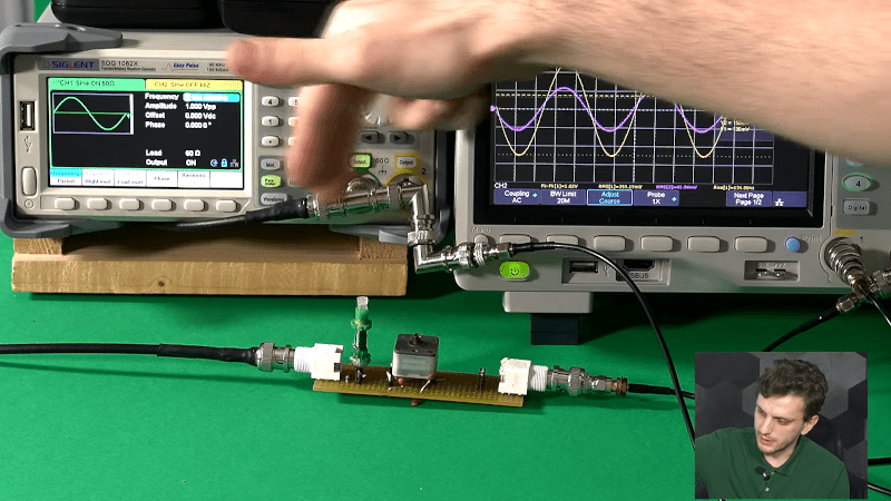
Matching is important for several reasons. Maximum power transfer occurs when the source and load impedance match. Also, at RF, mismatched impedance can cause reflections which, again, robs you of useful power. The video covers some math and then moves on to LTSpice to simulate a test circuit. But the part you are really waiting for — the practical circuits — is about 15 minutes in. Since the values you need are often oddball, [FesZ] makes his own adjustable inductors and uses a trimmer capacitor to adjust the actual capacitance value.
This is a big topic, but the first video is a great introduction blending theory, simulation, and hands-on. A great way to get started with a very fundamental RF design skill.
We’ve worked on explaining all this before if you want a second take on it. If you want to understand why mismatched impedance leads to less power delivery, we’ve done that, too.


Impedance matching in general used to be a bigger thing. But some of the more obvious is gone, no transformers at the output of audio amplifiers. Opamps may not do away with it, but they give near zero output impedance, so you’re not fussing with in between. And gain is easy so you don’t need to optimize to get enough gain.
It’s still a must in use cases where your leads approach wave length (RF) – reflections and resulting standing wave in cases where you have impedance mismatch are make or break in RF!
Answer this: If opamps have “near zero output impedance”, why is that impedance best for driving (say) 32 ohm headphones? Or 8 ohm loudspeakers?
Seems like audio amplifier matching to the real load impedance (i.e. resistance) of a speaker is a different question from matching the complex impedance of a transmission line or filter to an antenna or other load.
We lump the two terms together in colloquial English and call them both “impedance matching,” but it is two quite different problems.
It’s best because we don’t have any practical speaker that has a near zero ohm resistance, otherwise you’d expect to get some efficiency gains using one of those. So it’s effectively the best impedance we can get practically, but not theoretically the best
They’re both instances of the same phenomenon though, manipulating the impedances between a source and load to provide optimum power transfer. The exact consequences of failing to do so is different in each case, but they’re both following the same fundamental physics, having conjugately matched source and load impedance gives the maximal transfer of power for a given source or load. They’re different in the same way that drag racing and formula 1 racing are different, they’re obviously very different in the details but they both are still clearly forms of racing, sharing some fundamental ideas
Some simple math – I’ll use a DC example to make it simple – the same applies to AC
Case 1
12 Volt battery with 10 ohm internal resistance and a 10 ohm load
So 6 volts across either meaning –
3.6 watts lost internally
3.6 watts getting to the load
Case 2
12 Volt battery with 10 ohm internal resistance and a 5 ohm load
So 8 volts across the internal resistance and 4 volts across the load meaning –
6.4 watts lost internally
3.2 watts getting to the load
Case 3
12 Volt battery with 10 ohms internal resistance and a 20 ohm load
So 4 volts across the internal load and 8 volts across the load meaning –
1.6 watts lost internally
3.2 watts getting to the load
So you can see that the purpose if impedance matching is to optimize the proportion of available power getting to the load.
This is important in power distribution were you don’t want to much power being dissipated in the source potentially destroying it. And you don’t wan too little power getting to the load causing energy waste.
It’s also important in RF where in imbalance can cause low antenna outputs or destroy the RF output (amp) stage.
It’s not an objective with headphones to achieve maximum power transfer.
It’s much the same with speakers however impedance plays a role in damping factor.
With an op-amp the source impedance is still the power supply however and op-amp can be configured to provide a specific output impedance or input impedance as power supply internal resistances are very low with a regulated PSU.
So all the math and the terms still apply, it’s just that the objectives are different.
Umm… Opamps don’t have near zero output impedance. The are assumed to have a near infinite gain but actual current load they can drive can vary quite a bit.
Op-amps have quite low output power specifications because they’re an amplifier and not driver. The are exceptions with audio op-amps.
However if you have a low current load that is within specification then op-amps can have very low output impedance.
As someone who has designed RF circuitboards profesionally I have to chuckle at perfboard being used.
He’s using board dimensions of a few centimeters at a wavelength longer than 30 meters. ‘Sall good.
This guy knows what he’s doing.
Not this case but … the one that gets me is flux everywhere. Ah-la parasitic capacitance.
And this is one reason to not clean off the flux from some precision equipment. That flux can literally effect the accuracy of the device, and since it were likely there when the device got calibrated, then it is now part of the calibration.
Not sure where to start but I’ve worked in an engineering lab where baby engineers have had difficulty running audio over unshielded twisted pair over distances of about 10 meters. Nearly zero output impedance (unbalanced) and infinite input impedance (also unbalanced) with disastrous results. Installation of bookended transformers with a series resistor from the amplifier source, defining a source impedance, properly balanced and impedance (resistive on the secondary) matched transformer load, heck, you could run that audio 10 miles.
RF? Impedance matching dramatically reduces smoke production. It’s a matter of where you want the transmitter power to go: either out in the ether or dissipated as heat in your final amplifier.
Think traveling wave.
With RF we imagine a wire connection between the transmitter and the antenna. We should think more like a signal that is released from the transmitter and is sent on it’s way down a transmission line path with time delay along its length.
You can get reflected power and transmitter impedance mismatches from reflections that are from the antenna once the signal has jumped off the antenna and reflected off of nearby metal and coupled back into the antenna as well as mismatches from the antenna itself. It’s a visualization thing.
I used to explain it (poor SWR) as the antenna reflecting the power right back into the output driver (transistor or whatever).
It helps, too, to think about current and power, and not just voltage. Too often the new recruits have this notion that ‘ground’ is just some magical reference and the idea that voltage alone can convey a signal.
You have to deliver some actual power to get a signal across. Doesn’t have to be much, could be microwatts, but more is better. Just presenting 0V or 5V to an input of 10M-ohms or more will hardly cut it. It’s a signal to noise ratio thing; you want your sending unit to deliver more power to your receiving unit than will the local television transmitter or the fluorescent shop lights.
Sure you can use an op amp or FET or whatever Hi-Z as the receiver input, but stick 100 or 1K ohm ‘burden’ resistor at its input and make the transmit end deliver some actual current down that wire, and suddenly you’re getting the signal you want, and not whatever stray field struck your cable.
This of course means that if you send say 1mA down the ‘signal’ wire, you can expect to get that same 1mA back on the ‘ground’ wire, which is why the old timers tend to call that wire the ‘return’ rather than ‘ground’.
This bit about magical ground reference and return is a big deal with people learning.
I am no expert myself, but find I consistently need to go over fundamentals of current, loss and load these days. I suppose it helps me remember.
Apologies for the necromancy.