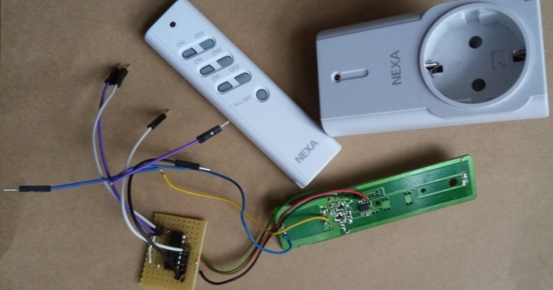
Bending various proprietary devices to our will is a hacker’s rite of passage. When it comes to proprietary wall sockets, we’d often reverse-engineer and emulate their protocol – but you can absolutely take a shortcut and, like [oaox], spoof the button presses on the original remote! Buttons on such remotes tend to be multiplexed and read as a key matrix (provided there’s more than four of them), so you can’t just pull one of the pads to ground and expect to not confuse the microcontroller inside the remote. While reading a key matrix, the controller will typically drive rows one-by-one and read column states, and a row or column driven externally will result in the code perceiving an entire group of keys as “pressed” – however, a digitally-driven “switch” doesn’t have this issue!
One way to achieve this would be to use a transistor, but [oaox] played it safe and went for a 4066 analog multiplexer, which has a higher chance of working with any remote no matter the button configuration, for instance, even when the buttons are wired as part of a resistor network. As a bonus, the remote will still work, and you will still be able to use its buttons for the original purpose – as long as you keep your wiring job neat! When compared to reverse-engineering the protocol and using a wireless transmitter, this also has the benefit of being able to consistently work with even non-realtime devices like Raspberry Pi, and other devices that run an OS and aren’t able to guarantee consistent operation when driving a cheap GPIO-operated RF transmitter.
In the past, we’ve seen people trying to tackle this exact issue, resorting to RF protocol hacking in the end. We’ve talked about analog multiplexers and switches in the past, if you’d like figure out more ways to apply them to solve your hacking problems! Taking projects like these as your starting point, it’s not too far until you’re able to replace the drift-y joysticks on your Nintendo Switch with touchpads!


Most of these 315/433Mhz work with a rflink gateway ( https://www.rflink.nl/devlist.php )
Reverse engineering these is an afternoon’s work. Then you realise there’s no state feedback and they’re useless as soon as someone operates them with the remote as well.
This!
Feedback is a must for computerised home automation.
The product itself is ideal for meat-based automation, where the fluid-filled optical sensors can detect that the switch is not in the desired state, and press the button.
I just solved the feedback problem on a thermostat I added onto a ceramic heater/humidifier. I also ran into the multiplexed button issue. I didn’t want to hook up to all the pins and reduplicate the entire control panel, so I ran wires to the 3 buttons I wanted to manipulate and used transistors to activate the buttons. Then to error correct in case of whatever problem I encountered (manual user input, bugs in implementation, etc) I ran photoresistors to each led and slid them in just below the LEDs which are stood up on their leads a bit. They also fit beneath the panel’s shrouds that luckily prevent accidental activations. My program runs in “blind mode” with an error check to compare the program state to the actual led output, and push the needed button the desired number of times to correct any problems. If everything matches up, it does nothing. You could just as easily give priority to the user input by electing to change the program state to match the LED output, but it’s really up to what your purpose is. I want to control the heater with the thermostat, not the other way around.
I’m about to solve my conflicting OakLED display and DHT22 issues with a digispark hosting the DHT and the OakLED running on the main Arduino pro mini, talking over i2c (I hope). I admit the recent article discussing this pushed me towards i2c over software serial. The ability to send data variables without parsing was a huge factor in the decision, but unfortunately that part wasn’t mentioned in the article. I’m not sure what’s causing the conflict, but it might be the display uses the i2c bus too much for the DHT to get a word in edgewise. I’m pretty sure they don’t have the same address.
I’ll submit it once I have everything worked out. It’s not so amazing, but I’m proud of it.
Are you sure you have DHT22, because DHTxx does not speak i2C. It has a protocol of it’s own.
No, you’re right. I was confusing it with something else. It’s definitely a DHT. I built that portion a couple of years ago and I’m now upgrading it to add in the error correction. It only has 1 wire for data. It’s not i2c, but it definitely conflicts with the OakLED. I’ve found others online who have had similar problems, but no solid solution. I’m going to try to fix it by sandboxing it with the digispark. It runs the example code just fine, so physical wiring isn’t a problem. Something else is resulting in NAN errors when in the thermostat running code.
I’ve just fine this both ways. Using three remote and an opto isolator and recording the signal on an sdr and recreating it. The former was much easier as I had to use trial and error to get the timing correct on the second. However the second will ultimately make a smaller device.
Here’s my take on the same subject: https://antibore.wordpress.com/2016/01/04/controlling-opal-branded-wireless-electrical-socket/
With most rf devices finding the protocol and code was not that hard. The devices that had a ‘rolling code’ posed a bit more of a problem.
With wifi devices so widely available at very affordable prices there is usually no real reason to try and automate an rf device except for curiosity, wanting a challenge or non replacable items