One day, [mitxela] got bored and decided to build his own HDMI monitor – the unconventional way. HDMI has a few high-speed differential pairs, but it also has an I2C interface used for detecting the monitor’s resolution and issuing commands like brightness control. In fact, I2C is the backbone for a lot of side channels like these – it’s also one of our preferred interfaces for connecting to cool sensors, and in this case, an OLED display!
[mitxela] describes his journey from start to end, with all the pitfalls and detours. Going through the pinout with a broken hence sacrificial HDMI cable in hand, he figured out how to probe the I2C lines with Linux command-line tools and used those to verify that the display was recognized on the HDMI-exposed I2C bus. Then, he turned to Python and wrote a short library for the display using the smbus bindings – and, after stumbling upon an FPS limitation caused by SMBus standard restrictions, rewrote his code to directly talk to the I2C device node, raising FPS from 2 to 5-10.
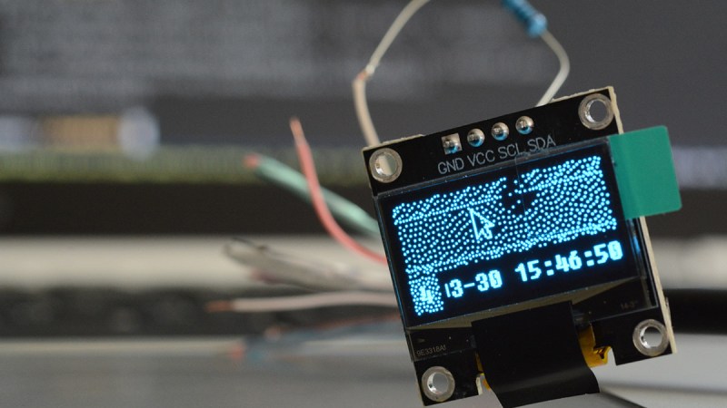
From there, question arose – what’s the best software route to take? He tried making a custom X modeline on the HDMI port the display was technically attached to, but that didn’t work out. In the end, he successfully employed the Linux capability called “virtual monitors”, and found out about an interesting peculiarity – there was no mouse cursor to be seen. Turns out, they’re typically hardware-accelerated and overlaid by our GPUs, but in [mitxela]’s case, the GPU was not involved, so he added cursor support to the picture forwarding code, too.
With partial refresh, the display could be redrawn even faster, but that’s where [mitxela] decided he’s reached a satisfactory conclusion to this journey. The write-up is a great read, and if videos are more your forte, he also made a video about it all – embedded below.
We first covered the ability to get I2C from display ports 14 years ago, and every now and then, this fun under-explored opportunity has been popping up in hackers’ projects. We’ve even seen ready-to-go breakouts for getting I2C out of VGA ports quickly. And if you go a bit further, with your I2C hacking skills, you can even strip HDCP!
We thank [sellicott] and [leo60228] for sharing this with us!


That’s a pretty dope unconventional way to kill some time with a cheap, small lil OLED display I’m sure many (including myself) just have chilling in their hoarded spare parts collection. 👌 Great job with the detailed video too 🤓
And If it would have run over a Tiny85 as USB-I2C adapter, it would have been an USB monitor?
Schlau me up!
Last time I run over an ATtiny85 I had 8 puncture wounds. That’s not actually so bad for someone who came from the days of 40 PIN DIP or even 64 PIN.
Pro tip, for anything over 16 Pin DIP, cut all the legs off and pull them out one at a time otherwise the pins rotate and slice their way out.
If your pulling the whole chip out at once then use long nose pliers with one (nose?) under the chip and one over the top to keep it parallel.
Yeah, new insult/retort “Go stomp on a DIP 68000 barefoot.” :-D
Hmmm, best put the spare chip puller in the first aid kit.
When I first read RöB’s message. I had a very clear memory of extracting a Z-80 from my foot using exactly that.
When I first read RöB’s response, I had a very clear recollection of using exactly that tool to remove a Z-80 from my foot at 2am one morning . (second attempt posting this, sorry if we end up with two posts)
SSI – Small Scale Injury
MSI – Medium Scale Injury
LSI – Large scale injury
And of course VLSI, Very Large Scale Injury.
I have a project similar to this I2C hack. I tapped into I2C bus of the Laptop Panel and add the ADC chip connected to the 3 axis Accel sensor. Wrote some C code to read the ADC value and use it to Auto rotate the screen (xrandr) of Samsung N510 running Debian.
Quote [Arsenijs Picugins] : “HDMI has a few high-speed differential pairs”
Well that’s an improvement in the terminology often miss-used. So often I read that HDMI signalling is LVDS – low voltage differential signalling as though LVDS IS the protocol that is used by HDMI.
If your sending signals at these data rates then your using Coaxial cable, Optical Fibre, Wave guides or LVDS (of some form usually over twisted pair like Gigabit Ethernet). In other-words the LVDS is a hardware specification and not a data protocol.
The protocol used by HDMI (and DVI) is Transition-minimized Differential Signalling (TMDS). The “Transition Minimised” is a protocol to help data rates at the hardware level “differential signalling”.
FYI: The actual signal level is closer to PECL than LVDS. PECL reference from the Vcc while LVDS is reference from GND.
https://download.tek.com/document/61W_17974_6_HR_Letter_0.pdf
>HDMI leverages on the successful transition minimized differential signaling (TMDS) technology. The differential
signals are +3.3 Volts, terminated in 50 Ω with nominal amplitude transitions of 500 mV (+2.8 V to +3.3 V).
The voltage swing can vary from 150 mV to 800 mV. The signals have rise times of the order of 100 ps.
For LVDS (from wiki)
VOL 1.0 V
VOH 1.4 V
You can level shift LVDS signal to HDMI probably as simple as cap coupled and DC bias.
Found it. It is CML. Slightly different than PECL in that it uses 50 ohms pullup terminations to Vcc.
So it can swing all the way up to 3.3V.
https://en.wikipedia.org/wiki/Current-mode_logic
> CML is the physical layer used in DVI and HDMI video links, the interfaces between a display controller and a monitor.
I see someone upping this hack with 15×17 of these oled screens for full HD display. Now, how to connect 255 HDMI cables to one computer?
I don’t know how you would connect that many HDMI cables but I think it might have something to do with a hydrolytic press.
Just need a few levels of I2C multiplexers to address all the displays separately. 33x TCA9548A should do it :)
So… could you use this with a microcontroller that outputs IIC and have it switch inputs, so that the monitor could display an HDMI source OR the MCU output based on the selected source (HDMI 1 or HDMI 2)? That would make my year.