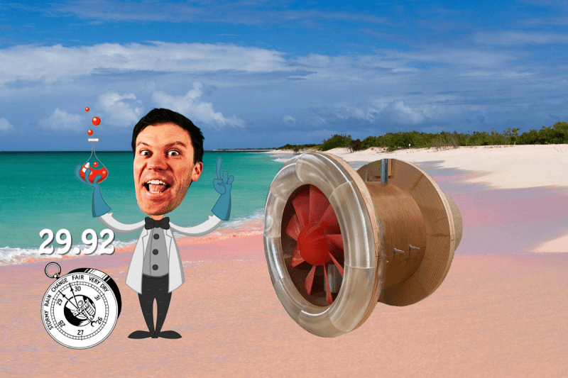
About a year ago, [Wyman’s Workshop] needed a fan. But not just a regular-old fan, no sir. A ducted fan. You know, those fancy fan designs where the stationary shroud is so close to the moving fan blades that there’s essentially no gap, and a huge gain in aerodynamic efficiency? At least in theory?
Well, in practice, you can watch how it turned out in this video. (Also embedded below.) If you’re more of a “how-to-build-it” type, you’ll want to check out his build video — there’s lots of gluing 3D prints and woodworking. But we’re just in it for the ducted fan data!
And that’s why we’re writing it up! [Wyman] made a nice thrust-testing rig that the fan can pull on to figure out how much force it put out. And the theory aimed at 652 g of thrust, which was roughly confirmed. And then you get to power: with a 500 watt motor, he ended up producing 47 watts. Spoiler: he’s overloading the motor, even though he used a fairly beefy bench grinder motor.
So he re-did the fan design, from scratch, to better match the motor. And it performed better than the theory said it would. A pleasant surprise, but it meant re-doing the theory, including the full volume of the fan blade, which finally brought theory and practice together. Which then lead him design a whole slew of fan blades and test them out against each other.
He ends the video with a teaser that he’ll show us the results from various inlet profiles and fan cones and such. But the video is a year old, so we’re not holding our breath. Still, if you’re at all interested in fan design, and aren’t afraid of high-school physics, it’s worth your time.
Don’t care about the advantages of ducted fans, but simply want to make your quad look totally awesome? Have we got the hack for you!


IF you are interested in fan design you should also check out major hardware on YouTube :)
Devil is in the details of the blade profile.
Airfoil, chord, thickness to chord ratio and design AoA are all concerns. Those values will change with radius. Tradeoffs everywhere.
The software tool, to start, is called xfoil. You’ll need to write a wrapper to beat on it. It does one section per run.
First tip: Trig based pitch calculations are good, but add in a design AoA (about 2 degrees to start).
Second tip: Under cambered airfoils make for nice light, stiff blades.
Third tip: 3d printed blades aren’t going to do well. These are highly stressed applications. You can’t give up that much strength.
3000rpm is very slow for an impeller of that diameter. Racers want propeller blade tips going about mach 0.75. Eyeballing R, that calls for about 20kRPM.
Get a better test rig motor, CNC carve your blades from wood for prototyping (mind the grain).
You can also look at ideal propeller blade theory to guide you. It’s a design process that targets producing the same air velocity at all blade radii. Web apps are out there. Google.
There is another software available that would work much better here and has been written by the same person- prof. Drela and it is called Xrotor.
Designing such fans have a lot of variables and the inner shape of the tunnel matters a lot, also some other factors like the structure supporting the motor and fan etc. I have spend almost 3 years doing research on ducted fan units – static, wind tunnel and CFD.
A single phase induction motor will never get up to the rated speed with such fan blades. Single phase induction motors have really poor pull-up torque, so they’re easy to bog down on starting – you have to let the accelerate before loading up.
https://1.bp.blogspot.com/-POLOO4TuPU0/TeqNYkuQUCI/AAAAAAAAAE4/AAV-gDjQdlU/s1600/19.JPG
If the speed ends up somewhere around 40% of the rated speed, the fan was grossly oversized for the motor.
Gram is not a unit of force
Its almost like mass has some correlation to force….. Perhaps via F=MA…
Okay then, in internet units, about 3 bananas, or approx 1/183 of a washing machine.
https://en.wikipedia.org/wiki/Gravitational_metric_system
But he actually calculates the thrust in Newtons, like you should, and then translates it over to force-due-to-the-gravitational-acceleration-of-a-mass.