We are spoiled for choice when it comes to single board computers, whether they be based around a microcontroller or a more capable SoC capable of running an operating system such as GNU/Linux. They can be had from well-established brands such as Arduino, Adafruit, or Raspberry Pi, or from a Wild West of cheaper Far Eastern modules carrying a plethora of different architectures.
Everyone has their own favourite among them, and along with that comes an ecosystem of operating systems and software development environments. There’s another aspect to these boards which has evolved; certain among them have become de facto interface connector standards for hardware peripherals. Do these standards make any sense? Let’s talk about that.
How Do De Facto Standards Come About?
In most cases, an interface standard is the result of an effort specifically to create it. Consider for example the USB-C port, instead of merely happening because a manufacturer decided to put a reversible high-speed data port with power capabilities on a machine, it was the result of many years experience and work on the part of an industry consortium.
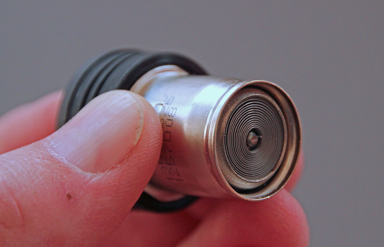
Sometimes though, an interface standard comes around by chance. The car accessory socket is by any standard a pretty awful power connector system, originating decades ago as the receptacle for an electric cigarette lighter. Because there was no other handy way to access a 12 V power supply in a car it became the power source for the few electronic in-car accessories that were available, and has since evolved into the standard automotive power socket. Oddly, many car accessory sockets are now unsuitable for their original purpose, being no longer designed to withstand the heat of a cigarette lighter element.
And so we come to the connectors on single board computers. Almost all of them have an expansion connector, which serves the purpose of bringing out as many of the available interfaces in one place as possible. Some are well designed and others not so much, but none of them are designed in the same way as the USB socket to be independent of specific hardware and with convenience for the desired application in mind. Instead they’re left to the designer of the board who may not expect the device to become a widely adopted standard and thus may not think ahead as to how their creation might be used.
None Of These Are Like The Others
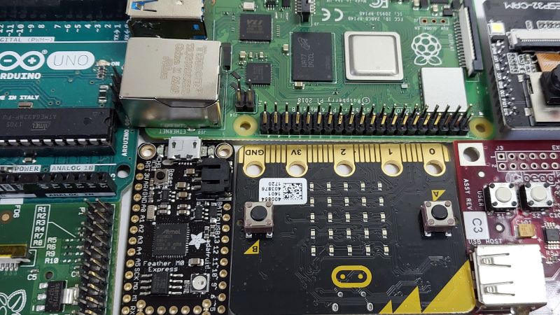
If we were asked to name some boards whose interfaces have become unintended de facto standards, those we’d end up with wouldn’t surprise most of you. The original Arduino, the Raspberry PI, the Adafruit Feather and maybe the Raspberry Pi Pico, perhaps the BeagleBone, and one we’re seeing more and more, the BBC micro:bit. It’s worth taking a look at these individually for a minute to work out what we like about them, and what we don’t.
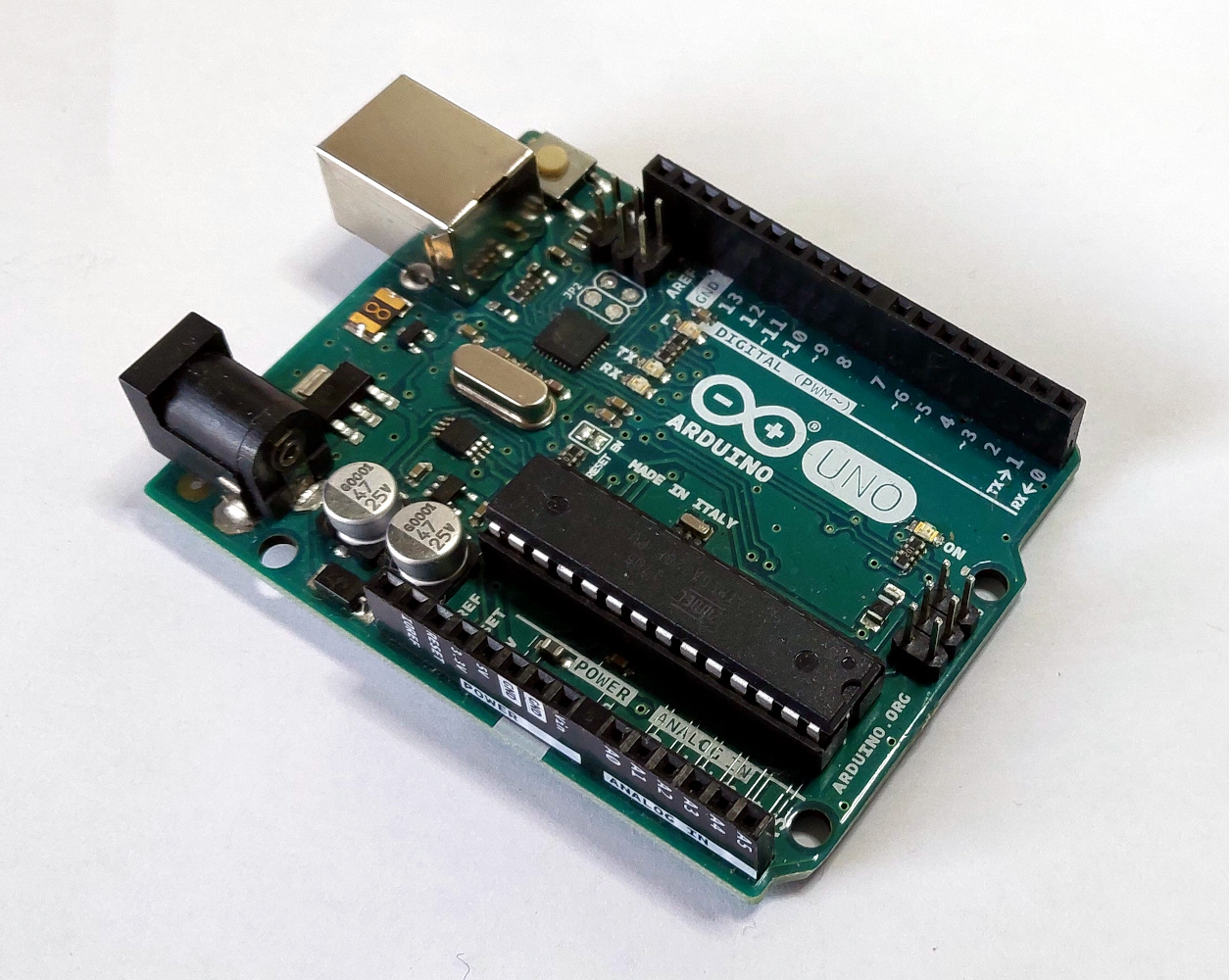
The granddaddy of them all has to be the Arduino. We don’t know whether it was the first board to give us the idea of shields, but it was certainly the one that popularised them. Before the Arduino it was more usual for a board to come with a prototyping area alongside a header with the I/O lines to which a daughter board might have been attached, the Arduino gave root to the idea of a family of add-on boards within a defined ecosystem.
We like the Arduino expansion pinout for its organisation of the different types of interface next to each other and in numerical order and we like its use of inexpensive 0.1″ pin headers, but the size of the thing and the need for two sets of headers so far apart looks distinctly unwieldy and old-fashioned. Don’t get us started on the odd row offset. Still, it’ll probably be a long time before we’re free of the classic Arduino shield because there are so many still available, but would it be a reasonable choice for a new design here in 2022? We don’t think so.
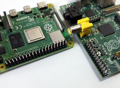
The Raspberry Pi 40-pin header and HAT form factor seems to have become a de facto standard for more powerful boards, typically those that run Linux. It’s a nod to the success of the little board from Cambridge, but for all the good things the Pi has brought us we’d say the expansion connector isn’t one of them. It’s a victim of the Pi’s genesis back in 2012 from a then-tiny organisation producing what they thought would be a relatively small run of a board that was at the time barely out of prototype status.
The first Raspberry Pi boards had component and routing choices based upon expediency and the resources available to them, so that the lines were brought out to a header at all was the most important, and not arranging them nicely for a mass market board that would dominate the sector a decade later. Thus the original 26-pin interface and the 40-pin extension that followed have the various interfaces scattered haphazardly around them, and we’re certain that were they to do the same job today they would bring some order to it. We like the use of a single 0.1″ header, but even though we understand why it’s that way, we can’t say the same for the arrangement of pins.
The dual-in-line boards such as the Feather, the Pi Pico, and the various smaller Arduinos, have a very convenient approach to expansion, following the same path as the larger DIP ICs of the past. Thus an Arduino Nano will often be found mounted on a piece of stripboard or a PCB, or plugged into a breadboard. The Feather and the Pico take this further, with both sorting add-on boards that piggy-back upon them. We like them for their well-thought-out pinouts, but we think a single connector gives more flexibility.

Finally in our list of boards is one that takes a completely different tack. The BBC micro:bit is an educational microcontroller board originally designed for British schools, and its expansion connector is a PCB edge connector with five large pads for crocodile clips and 4 mm plugs to make life easy for kids, interspersed with finer pitch connections carrying other interfaces. It’s well designed and an attractive enough choice that it’s appeared on quite a few competing boards, but it relies upon a more expensive specialised edge connector receptacle. We like edge connectors, but not ones which need an expensive connector.
It Could All Be So Much Better
So having surveyed the field, we have a range of what are essentially proprietary standards which have been adopted by others. None of them are the perfect solution to SBC interfacing, so our next question is: what would be the qualities we’d look for in something better? It’s a conversation we think the industry should be addressing, but how do we think they should address it?
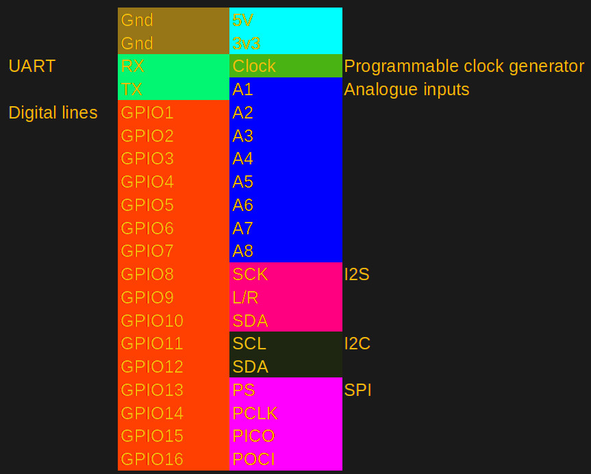
Perhaps the best place to start is with the connector itself. Here the Raspberry Pi gets it right with standard two-row headers, they’re cheap and readily available without forcing a board form factor as the Arduino or DIP format boards do or requiring a special connector as the micro:bit ecosystem does. Then the next area to consider is the pinout. There is no reason that digital GPIO, analogue lines, and interfaces such as SPI or I2C can not be arranged on sequentially numbered pins for easy interfacing.
We think that microcontroller and SoC interfaces are all similar enough that this could be achieved. We also don’t think there’s a particular commercial advantage to manufacturers in having their own proprietary pinout, because in this context there’s little value in exclusivity. A common pinout across multiple boards shouldn’t take a multi-million-dollar industry consortium as it does with USB, instead a simple set of I/O lines have to be wired to a set of headers.
The reason it hasn’t happened yet is probably that there’s been no immediate sales incentive for them to do so, but we think there’s an angle there which might prove persuasive. Hardware manufacturers should imagine a world in which aside from all SBCs having the same interface, all expansion cards, shields, HATs, or wings, have it too. Suddenly the potential market for a card becomes much more lucrative, and since all the major SBC makers also sell cards we hope that they too can see the potential.
We’d be interested to hear from our readers on this subject, what do you think?


2.54mm pin spacing for the win.
I have angry Europeans for you on line… all the lines. :P
The only thing worse than 2.54 mm pin spacing is having 2.50 mm pins on the market at the same time…
Don’t forget 5.08 mm (0.200 in) and 5.00 mm (0.19685 in)!
1/8″ and 3 mm bits? Why not have both? Get your calipers out to tell which is which!
And 1/4″ = 6 mm. On eBay.
2.54mm is fine. Imagine if we used some really wild unit, like lb of copper per square foot
bahaha he said get your calipers out lol got me
As long as it’s a standard I don’t care if it’s measured in chains and firkins – 2.54mm spacing is still insanely common and no hardship to deal with, honestly I’d vote for it above all else unless you really need more density.
Indeed. It’s “2,54 mm”, also. Not “2.54mm”. We’re using the comma. And a space character. 🙂
Well, except the UK, maybe. But it left Europe behind a while ago.
See https://de.wikipedia.org/wiki/Dezimaltrennzeichen
2.54mm is perfectly acceptable for us and full conforms to SI, just as long as it isn’t 1/10″ ;)
Heheheh nice. Suck it, rest of the world
I don’t think there can ever be one universal standard for SBC as they have too many users trying to do too many different things with them. What suits one design constraining situation will be hopeless or at least very inconvenient at the others – like the CM4 connectors really great for compact high density connectors, but difficult to prototype with, tight tollerance makes using more than one tricky (and technically ‘wrong’) and it doesn’t have the cycle count of 0.1″ headers for instance.
Nearest I think is plausible is having a layout pattern standard or two making converting between ‘standards’ on different connectors a bit easier to route. But even that is likely to be tricky – high speed signals are becoming common and need a great deal more care than low speed to work at all. It may not matter to most of the projects you see on HAD if its running 10x slower than the IC potential because the layout forces it to but…
In my world dictatorship, I would decree that they all must be encased in a glass envelope and fit into an octal socket. Need extra pins? There’s always the anode post on top
There’s a huge difference between prototyping a few boards and designing a board for millions of users. I agree not many users here are trying to build the next Raspberry Pi- but look how many people use a stock Debian. Software is “cheap” and hardware is not, but kernel developers organized in the 1990s and built an operating system. A shared SBC can be developed for those who do not need a specific number of things- just a basic computer that can run Raspbian (now Raspberry Pi OS) with LXDE. But does the Rpi really serve the open hardware community? It isn’t an open standard, and I can’t put a Rpi4 . Community organizing is an old technique- if you want something that a number of people want- you organize. If you don’t, fine. But it’s just a technique that works. Some compromises are sometimes made, whether it’s an individual or a group action. But some group actions achieve greater results because it pools greater resources- things like crowd-funding, etc.
Something as miniscule as mounting holes-makes a huge difference:
If one examines the MicroATX and Mini-ITX form factors, you’ll notice that the mounting holes overlap on two of the sides. So a form factor may use, 4 6 or 9 screws, depending on the size. SBCs do not even have to be the same size to match. They just need to overlap in 4 areas, so that the mounting screws can be used in the same location for the smaller boards, and left empty for larger boards. A larger SBC could use 6 mini screws (not the size as the ones on the ATX cases).
The problem is not really form factor or mounting holes, it’s connectors, pin out and voltages.
It’s nice to be able to mount a new board in the same place as the old one, but if you have to redesign the remainder of the system because the new board has different connectors, an other pin out or uses 1.1 instead of 3.3V you haven’t won much.
There is an attempt to unify SBC I/O, see 96boards. Quite a few SBCs followed the standard. Turns out, use cases vary more widely and even this set of I/Os is not enough
The 96boards I/O effort is a reasonably good standard as it gives 40 pins for low speed and another 60 pins for high speed. Requirements for low speed are:
* One UART w/ optional 2nd.
* Two I2C
* Power and Reset signals
* One SPI
* One PCM/I2S
* Twelve GPIO
Yep. And I got into its limits very quickly, as I needed 5 UARTs (rs485) and 2 CANs, along with sone more stuff, Ethernet included. Stretched the GPIOs provision on Ultra96 and required some hacks to get around. But yes, this standard is better than most indeed, with at least some potential for scaling.
The Beaglebone uses pins, that serve multiple purposes, but that has still allowed a somewhat grouped arrangement and a (somewhat) sensible numbering scheme.
Unfortunately, some (many) of these pins are reserved for other purposes (HDMI, eMMC etc.), requiring device tree modifications to allow using as many pins as possible.
The Arduino was the first to offer stackable shields?
Well…….. There were others before then.
Here’s one that was pretty late to the game, but I can’t remember back farther than this. (Ha)
https://pc104.org/hardware-specifications/pc104/
Back in the old days, we used to buy lots of these for prototyping because we could get function-specific modules that plugged right on top and building systems was just so much easier and rugged than using a motherboard and ISA cards.
@bornbefore2000 I came here to mention the pc104 specs. I have several ampeg computer on board pc104 systems kicking around. It’s a great standard and you start with the computer on board and just stack modules as needed. It’s the original Arduino if you tthink about it complete with “shields” to get what you need done.
Not ampeg no no Ampro pc104. Brainfart:(
http://www.stackpc.org/ tried to get an update to the PC/104 standard more recently that would have incorporated some of the recent suggestions. And Nvidia used the Micro ITX form factor for TX-2 before going off the rails for the Nano and other versions.
There has been some debates on why Nvidia isn’t compatible with PC/104
https://forums.developer.nvidia.com/t/common-reset-line-for-all-pcie/112131/4
But in the case of RPI and other similar computers mentioned above it seems to be more of a COM debate verse a SBC debate (https://en.wikipedia.org/wiki/Computer-on-module).
I think if you take a look I say it was the first to popularise them. Not that it was the first.
actually if car socket connectors were made like the original cigarette lighters with sturdy bulge to hold them firmly in place, it would not be bad at all.
True
Anyone remember PC/104?
PC104 is however in a completely different area.
The interface between the boards is just the system bus itself. Ie, high speed serial as far as the eye can see.
The rest is handled by the various cards in the stack up, providing additional features like GPIO, serial, analog channels, relay control, GPU coprocessors, networking, etc, etc.
The standard has though switched to PCI, and now to PCIe. It is little more than a daisy chain of PCIe cards these days.
This can technically be done on SBCs too, just have a UART and make a protocol for daisy chaining add in boards and you are now there.
Does this make blinking an LED easier?
Or driving a motor?
Or anything else?
Remember? It’s on my NuXT for the VGA :D. Seriously though, PC/104 is ISA, not GPIO, and hence has a _lot_ of pins…
PC/104 is a perfect example of why there can’t be a universal standard. PC/104 is based on the ISA slot that worked just fine for 16 bit Intel-based PC-XT-compatible computers. Which was fine for its time, but pretty much irrelevant today. The same goes for other standards, determined by the limitations of the devices they were designed for. The Arduino pins? Not enough pins for microcontrollers that need to interface to way more pins, e.g., for LCD panels, that the AVR series wasn’t really capable of driving anyway, mainly due to RAM limits. So for micros that COULD refresh an LCD panel, the 40 pin header we see on Raspberry Pi has become the next de-facto standard. Which will also be fine until it isn’t.
You forget the standard has been updated several times with Pci express version in 2008.
Does anybody remember the EFS connector?
It was used in the Robotron EC1834 PC, for example.
It was a more professional version of the PC/XT bus. Pins vs edge contacts, 3 rows..
The Arduino Uno footprint should be banned as a crime against humanity.
+42
+42^2
+42^2^2
+42^42
+42^42!
+1
I think the mechanical stability provided by the spacing between the two rows of headers is very under-appreciated.
Come on, just no. You’re making light of real evil with that comment. Forced famines are crimes against humanity, as are concentration camps, digital identity domestic ID cards, mass online surveillance, facial recognition and corporate censorship. One could perhaps broaden the CAH definition to also include proprietary software, especially where dependent on regular check-ins with cloud servers… But I don’t see anyone having their fundamental liberties violated simply by a not too well arranged set of 2.54mm headers.
Amen brother. Its kinda like ORCAD or Syteline. Those SW engineers should be immediately fired and banned from ever writing software again.
SBCs are about rapid prototyping, so this indicates that header pins are the right approach.
The other problem is that each micro controller has different pin functionality. So if you standardize a header and a micro controller doesn’t support X pins but has pins that the standard doesn’t have, what do you do?
I was just reading an article from 1980 where they interviewed bill gates about IBM wanting to partner with his company to produce the 8088 personal computer. He kept going on about 8-bit verse 16-bit and made me realize that computers back then where what micro controllers are today. It’s a basic realization, but I hadn’t put much thought into it.
But we already have a standard. ISA, AT, etc. It’s the personal computer form factor. If you want to force some kind of standard.
But as I stated initially, these boards are about rapid prototyping and we should make it easier for a low run production ready device to be made. It’s the pain point at which I stop development on my electronics projects.
As they are also about being used directly in embedded applications as well it is not that simple…
Its not the old days were every electronic devices brain HAS to be an ASIC once in production so anything else is of use only for development. Now ASIC are actually more expensive and problematic to produce than they are worth most of the time compared to just integrating the much more versatile SOM or SBC into your product.
ISA cards are really awesome in term of connectivity physics : simple edge connections. But the bus seems to be very cumbersome to use.
I didn’t see anyone creating a ISA daughtercard with some MCU yet. That would be a very interesting idea IMHO. Very much like the SuperFX chip on SNES cartriges.
Did exist in the form of transputer card, I think. Or the chess cards.
See “TASC ChessMachine 512k”, for example.
https://www.schach-computer.info/wiki/index.php/Tasc_ChessMachine
This was a chess computer on an ISA card (PC/XT-bus card, more precisely).
Found this video:
https://m.youtube.com/watch?v=5qA5jtL_01U
Complete waste of time. Standards for interfaces are only relevant to mass production and plug and play interoperability and that entails more than just pin layouts . Accommodating all manor of processors and microcontrollers would make the connector huge and/or likely require some type of standardized glue logic to be universal. This would make inexpensive boards more complicated and more expensive.
Kind of like a SCART standard for SBCs :)
Mass production is still a cost-efficient solution in the long term for those who want to use a form factor without needing to new design enclosures which cost $$..There are at least two aspects to the standardization of SBCs. What’s on the board, and what dimensions/orientation the board is. Those are two independent planes that delineate why standardization is so beneficial in multiple senses of the word. One does not have to standardize the GPIO pin layouts, but can still standardize the maximum board size and so that it can be plug and play- i.e a DSI connector or embedded displayport rather than hdmi.
The problem is that many microontrollers offer features that your simple pinout won’t make available. What happens when you have a second I2C or SPI or UART? What about microcontrollers that have multipurpose interfaces? (You might, for example, have three ports that can be any of those things.) And some now have a connection matrix inside that allows the peripherals to be assigned to any of the available pins, or at least to multiple possible places.
There are of course already multiple standards for single boar computers, and the most obvious is PC104, and later extended with PCI-express compatibility.
But computers have changed a lot and those big pin count parallel buses have gone out of fashion.
Pico-ITX and Nano-ITX are also pretty small:
https://en.wikipedia.org/wiki/Mini-ITX
Although I think they just define board size, mounting holes and external connector shield location Ah, “Shield” is a good name for that rectangular RF shield that fits around custom connectors to fit in a standardized hole. None of that electronics boards named “shield”, Cape” or whatever, there must be 20+ names for those.
The 40p connector as used in the raspi’s will probably stay the closest to a de facto standard for the near future, but I’d like a more formal standard. I never looked too deep into it, but that 40p connector is also used on quite a lot of other boards, such as the Banana and Orange pi’s, Radxa Rock series, the Odroid’s from Hardkernel and there are more of these things with a 40p 2.54mm pitch dual row PCB header. I have not checked how much pin to pin compatibility there is between these PCB’s. Anyone reading this with experience in that area?
Another thing I like very much about that connector layout, is that it’s compatible with flat cables. This makes it easy to make one-off experiments on either breadboards or matrix (vero) board.
——————
Other SBC’s tend to maximize on pin count. for example the Beaglebone Black, Cubie Boards and the Olimex boards. As far as I know there is no exchangeability of daughter boards between them.
——————
But overall, I’m more interested in software standardization then in hardware standardization. For example “Raspian” used to be a specialized distribution, but it seems the software guys are cooperating and it’s now a (nearly) stock Debian.
https://www.debian.org/doc/manuals/debian-handbook/sect.raspbian.en.html
” But computers have changed a lot and those big pin count parallel buses have gone out of fashion.”
Even down to our microprocessors (fabric) going faster is easier than going wider. Going optical will help even more both in that goal, and eliminating ground loops.
PCIe everthing
PCIe is awful. It may have a good throughput, but the latency is atrocious and unsuitable for any hard real-time applications.
for example the jetson nano use the same 40 pins header but the the pinout is not compatible with raspberry so you can use all the raspi shield with this board.
so, whats the benefit of using same hardware pinout if you just can’t use it in software?
yes, and board size is not “just” a minor standardization. It greatly benefits the recyclability of a chassis- for example the pi-top v2 lets me use a Raspberry Pi 3B+ in the laptop, but I cannot upgrade the laptop to a Rpi 4B because the orientation of the HDMI ports and potential mounting holes/screws are all different: https://iotmote.substack.com/p/welcome-to-my-blog & https://hackaday.io/page/13394-amortization-of-open-hardware-development-costs-approach-0
Does any one here remember or did anyone here support the Microduino kickstarter?
https://www.kickstarter.com/projects/microduino/microduino-arduino-in-your-pocket-small-stackable
It seems to be an ecosystem that tried to solve this problem to some extent. Must not have been too popular since their website is down right now.
Basic concept was stackable modules with standardized pinouts. They had several different ‘core’ modules with various microcontrollers, and then a fair amount of expansion modules.
Kinda similar in concept to the Adafruit Feather: https://learn.adafruit.com/adafruit-feather/feather-specification
They are still active- that website was discontinued and this is a new one: https://www.microduinoinc.com/ you can also tell how active a company is by how recently they (re)tweeted, replied or liked something on twitter https://twitter.com/Microduino Thanks for the links!
Needs more ground pins distributed over the header, for shorter return paths and reduced crosstalk. (If you ever want to do high speed stuff on the gpios.)
And please don’t place the analog pins next to digital pins, or clocks *shudder*.
Please group the analog in one end of the connector, and preferably a pair of ground pins before the digital stuff.
+1 – hurrah for EMC and SI!
I did call it the shitty interface, and I hope you can gather that it’s firmly tongue in cheek.
Standardizing this is likely a futile effort to be fair.
Different pinouts brings forth different pros and cons. And depending on the applications it can be more or less handy for a given setup.
The Aurdino has the advantage of a more mechanically robust connection thanks to its wide nature.
The Raspberry pi is more compact, but not instilling much confidence as far as flexing goes and the pinout is a bit too mixed up without any real logic to it what so ever. (Personally would have had pin 1 be ground, 2 for 5 V, so that powering the board this way is trivial. Having the first available ground on pin 6 is odd.)
Other boards have their own sets of pros and cons.
I personally think these “hats” are inept to begin with. And I do find it much easier to just have the connections neatly wired to another board, where the other board is allowed to have suitable dimensions for its needs instead of crammed to fit in a stack of boards.
And these “hats” fails harder when one wants more than 1. Sometimes datelines aren’t routed through correctly, or as one expected them to be. Other times there is conflicts over IO pins, even if there is other pins available, etc, etc…
However, having a small standardized GPIO connector would be nice.
Like a 5 pin connector with 4 GPIOs and a (reference) ground would be nice standard. (pin 5 for ground. 1, 2, 3, 4 for IO.) If this is just a pin header, “molex” or other connector doesn’t largely matter.
For serial buses the same logic can apply, as an example for RS232/485 pin 1 and 2 can be Tx, 3 and 4 Rx. (1 and 3 being positive, 2 and 4 negative for polarity’s sake.)
A connector like this would just need a label explaining the function, like if it is digital, analog, serial, or something else. And perhaps a “max input voltage” if such is deemed necessary. (One can in general assume 5 V as standard. Else it should preferably be written on the silkscreen besides the connector, or clearly along the edge of the board near the connectors.)
Then a board can just have a row of such connectors for whatever needs one desires.
Fahnestock clips! That should be the standard!
Just kidding of course. Although the way they only require a stripped end to connect to would be nice in some beginner applications…
Really though, all the “there can never be a standard” responses make me sad. I want to see a standard. A standard in hobbyist SBCs is the one thing that I think might make a standardized, upgradable laptop a thing… sort of.
Imagine something like the Pi-Top only at a reasonable price. With a standardized connector you could just buy whatever SBC you want and slap it in there. When it comes time to upgrade, pop it out and pop in the new one. That would be so awesome! Not that I’m going to hold my breath waiting…
Nah, the little spring binding posts on the radio shack XXX-in-1 electronic kits.
One thing I would love to see that would help with coming up with a more-standardized connector/pinout is an addressable SPI bus. Similar to I2C, the first byte sent after chip select would be an address for a device on the bus. This bus would provide the speed benefits of SPI with the expandability benefits of I2C, where you wouldn’t have to dedicate a chip select line for each and every device. With something like that, you could have a ‘standardized’ connector that provided a UART, I2C, and (addressable) SPI bus which is probably enough for most purposes. Anything else needed could easily be expanded on top of one of those buses.
If you run out of chip selects, or think they are wasteful, just use an I/O expander.
Sure, an expander is one option, but not really ideal.
If you put the expander on the MCU side of the connector, you still have the problem of how many chip selects are ‘enough’ for a standardized connector/pinout. That will invariably mean a larger connector to get ‘enough’ chip selects, and still a few applications where there aren’t enough.
Putting expander(s) on the other (devices) side of the connector is more wasteful, but would technically work, as long as they can share that single chip select to begin with. I haven’t researched SPI expanders recently, so I don’t remember if they can co-exist with a single incoming chip-select, but if I recall correctly, they would each need their own which brings us back to the problem of multiple chip selects on the connector. I suppose you could use an I2C expander on the devices side, but that gets even more complicated.
I actually prototyped my idea a while ago using a $0.03 Padauk MCU with some code as an addressable chip select ‘expander’. It seemed to work pretty good in my limited testing. So, I have a bus with a single chip select plus SCK, MOSI, and MISO. The single chip select went into multiple Padauk MCUs (one per external board). The first byte written would be processed by all the Padauk MCUs and then they would ignore all further communication until a new chip select. Whichever one matched the ‘address’ would turn on its corresponding output chip select line to allow its child SPI device to communicate for the test of the read/write bytes. Once the shared chip select was pulled high again, the ‘selected’ Padauk MCU would also deselect the output chip select disabling the child SPI device again. So, the concept works find, but unless/until the address was made a standard and integrated into SPI devices, it would require glue logic to implement.
PlayStation controllers and memory cards use SPI and work something like what you suggested. While there are separate chip select lines for controller 1 and 2, memory card 1 shares the chip select line with controller 1 and memory card 2 shares the chip select line with controller 2. Depending on the first byte sent, either the memory card or the controller will respond.
It’s certainly attractive as SPI can be a lot faster then I2C. An MCU with 2 SPI could for instance use the first byte for addressing and select the devices accordingly. That could even be chained. You could of cause use a number of I2C addressable muxes for the SPI instead.
Hell, if you really wanted you could implement adresses and ethernet like switching in a network.
The magic of shift registers isn’t universally known.
But they sure make accessing an arbitrary amount of chips a breeze.
2 pins is all that is needed. One for shifting over the position, and one for reseting the registers back to its initial state where the first chip is selected.
The only limit is the fanout of the SPI drivers themselves. Eventually the input capacitance of all the chips just loads down the signal too much.
I3C is kind of a hybrid between I2C and SPI…
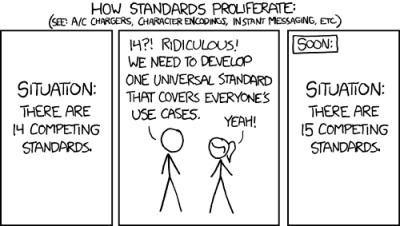
Where’s that XKCD comic about standards?
Just read the comments and you see that it is not a comic but hard reality. Everybody is suggesting something else.
Or read the article, the comic is right there.
er… in the piece above?
id like to see a standard pinout for soc modules with the intended goal of being able to slot any soc into any gadget. everything from phones and tablets, laptops, network appliances, etc, and then only have to deal with the problem of drivers.
for dev boards i always liked breadboardable pinouts and cheap connectors. but there is a middle ground where your microcontroller is way too powerful and you need higher quality connectors to handle the throughput, and usually at frequencies where breadboards are out of the question.
>id like to see a standard pinout for soc modules with the intended goal of being able to slot any soc into any gadget.
Seems like that standard is sort of happening organically with the Pi CM4 and its ‘compatible’ bretherin, some of which add yet one more of those board to board connectors. The family of CM4 like modules with a fairly wide range of specs and features really is growing into something along that line.
Yeah the CM3 looks nice https://wiki.radxa.com/Rock3/CM/CM3
Yes, I also write about this- the idea of a credit card-sized SoC would have immense benefit to building snap-on phones, tablets and laptops. I write about this idea here: https://iotmote.substack.com/p/welcome-to-my-blog https://hackaday.io/project/177716-the-libre-autarkic-laptop and https://hackaday.io/page/13394-amortization-of-open-hardware-development-costs-approach-0 The mini-ITX standard was the smallest, yet open source could make it even smaller. So that whenever someone wants to design an SoC, they could upgrade their laptop by using the same orientation of soc- where the usb and hdmi face outwards-towards the back, etc and have the same mounting holes like ATX cases.
Giovanni, that idea is basically EOMA68 and EOMA50 – reusing PCMCIA and CompactFlash Form-factor and connectors.
Hi Luke,
All form factors can be somewhat meta in their own right. PCMCIA is a wonderfully compact form factor, and I like it, but a slightly different computer+motherboard with more flexible I/O ports can be useful.
The comment below by “b smith” mentions computer on module https://hackaday.com/2022/10/05/the-state-of-the-sbc-interface-ecosystem-is-it-time-to-design-a-standard/#comment-6519034 This is closer to the form factor I’m targeting, because it allows the same size form factor to be upgraded to boards that use new display connectors/ports while still using the narrow space of the laptop. The EOMA68 would be using the same display driver/bus, potentially limiting the output of refresh speeds. If I wanted to connect an e-ink display with embedded displayport, instead of DSI how would I swap monitors while using the same chassis? The Quartz 64 contains:
“Embedded DisplayPort (eDP)
E-ink display connector
MiPi DSI 4 lanes
MiPi CSI 4 lanes”
https://www.pine64.org/2021/06/15/june-update-new-hardware-and-more-on-the-way/
What I’m suggesting is that a system-on-a-chip, or single board computer, maximize the I/O access so that future upgrades do not require a significant modification or replacement of the display frame. That is, it would need to be compatible with reflective displays, transflective (as in Pixel Qi), e-ink, as well as other displays. A mini-ITX allows this. A smaller one such as a credit card might not fit those kinds of connectors, but nonetheless the credit card size form factor should be pursued, just in an “open-air market”, rather than enclosed per-se. The keyboard and trackpad, I know less about standard drivers, but ideally the I/O is connector based, rather than integrated at a separate module (e.g. one I/O hub for keyboard/trackpad, microSD, etc).
It would be ‘nice’ if the pin 1 end of 2 rows of pins would be standardized. Let the other GPIO pins fall where they may. The standardized section would always be power 5V, 3.3V, GND, SPI, I2C, and a UART and maybe couple of general purpose digital I/O pins could be there too. That would be it. Keep it ‘simple’. Most add-ons/hats/etc. are going to use these pins in one way or another anyway to communicate with host SBC. These other pins (more power, analog, digital, gnd, etc.) would be board dependent for ‘features’ to differentiate boards from one another.
We’ve started toying with Jacdac which is like the USB of microcontroller connectivity. It’s going well so far, and is open source (despite being from Microsoft!)
Was hoping it’d get a mention in this article, sadly no.
this is why i created EOMA68 (and other Standards), beginning almost 10 years ago, now. the situation has not changed in that time, it has only gotten worse and more prevalent. designing standards is HARD, and there has to be an incentive to use them, even if it is a de-facto one (Arduino “shields”). PC-104 is still a highly-successful Industrial Standard, being based around the original IBM AT/XT PC de-facto standard: the form-factor just got smaller over time. everyone wants to make money: this is what drives them to use standards. otherwise they will do what is cheapest for them in this SBC market.
Some time ago I was building a microcontroller system that involved multiple microcontrollers (Pi, Pi Zero, Arduino, ESP) with multiple peripheral boards. I found the shield/hat approach didn’t work for many reasons. So, I devised a simple low cost backplane for my system. In the process, I came to the conclusion that 2 classes of connector were required. The first was for interboard connections that nowadays often use I2C or SPI, although sometimes other serial protocols like RS485 or Canbus are used. This, plus power distribution, was handled by the backplane. The second was for connections to outside the system. This included Ethernet connections, antenna connections, some long distance serial connections (such as RS485) and connections to sensors and actuators (e.g. motors). These are harder to standardize into a single connector, so I used individual connectors such as RJ45, directly off individual boards, for each external connection. Maybe it is time to introduce a standard backplane style connector for microcontroller systems. This would need to be a right angle connector covering (as I did) I2C, SPI, serial (for canbus etc), power distribution (5v, 3.3v and “raw” power) plus a few GPIO for SPI, interrupt lines and reset. I used cheap single row 0.1 inch right angle connectors with the option of upgrading to dual row for more complex systems.
One of the issues I haven’t seen mentioned is the issue of voltage. Some SBCs, like the early Arduino boards work at 5V. Some like the Raspberry Pi work at 3.3V. It’s not hard to design an interface that can handle either of those, and switch between them. How do you design an interface that can handle both logic levels at the same time?
And 96boards I/O is 1.8V… At some point LVDS will become more widely used, at 1.1V…
I may be wrong, but I see two problems on the power side:
– if you want to power a 3.3V SBC with a 5V power supply, you must add a voltage regulator, that will waste some energy. More over, simpler voltage regulators (LMXXX) require to have a power input greater that the output, so to power a 3.3V SBC, you may need to use a 4V power supply
– if you want to power a 5V SBC with 3.3V you should have a power boost buck module, it will add some components to the board and will also dissipate heat
In the end, you will need more components on the board, which is already space constraint, and you will lost some precious energy.
I will add that “P=UI”, so to have 10 Watts at 3.3V, you must have ~ 3 Amps: this requites thicker traces, and thicker cables. So for a raspberry PI it makes sense to power it using 5V, because it will require only 2 amps to make 10 Watts.
It’s not only the power supply voltage but also the IO voltage. Many modern SoCs have IO at 1.8V or even 1.2V (even for simple things like the console UART)
The best market might be in selling adapters to adapt between the existing interfaces and the one standard to rule them all.
Also, can we not call arduinos or microbits “single board computers”, they are not, they are microcontroller dev boards with inbuilt programming interfaces and power regulation. To be an SBC the chip on the board must be running a full OS, not just a firmware piece or a single piece of proramemd software, and have things such as a filesystem for storing multiple files in folder structures and some form of user interface like a terminal, ssh or GUI when correctly connected. The Pi or beaglebone are SBCs, as are various Pi “clones” using different chips for similar ideas, but arduinos and microbits and ESPs are definitely not SBCs.
You forgot the https://www.sparkfun.com/mikroe standard which is an attempt to intentionally design a pinout.
Feather is the most successful in microcontrollers I think? I’m quite interested in building compatibility layers between the various standards.
You do end up with some fugly looking things! https://github.com/rosmo-robot/Feather-Bit/tree/main/v1
https://github.com/rosmo-robot/Feather-Bit/blob/main/v1/daughter_concept/Readme.md
No standard is required IMO. Things are fine as they are, as long as there is an accurate data sheet.
STEMMA/JST-PH is great for i2c. Let’s specify a few cabled connectors for more flexible layout, or else use an unofficial alternate mode with USB-C(Can you safely use the 2.0 pins for I2C?)
A 12v pin might also be a good idea. As would some kind of always on power pin that could be powered directly from a battery for RTCs and boot electronics.
2.54 male pins would be great because male crimp pins are terrible.
It would be good to specify how power is supplied. As in “Any device can supply to the 12 to 24v bus but must tolerate other supplies by using a diode”, and the same rule for the always on power pin.
That way things like solar can be fully within the modular system.
But we can still do better than stackables. Why not define a whole set of cabled connectors instead?
4 pin PH is already taken by STEMMA, just use that. 5 pin PH can be GND/3.3v/5v/24v/sub5v battery. Or maybe battery should be allowed to go up to 15v and tiny things like RTCs can just have their own regulator for a few uA.
6 pin can be GND/3.3v plus 2 inputs and 2 outputs, and that can be used for GPIO, UART, SPI, and I2S.
I like the 5pin I2C & 7 pin SPI by https://shop.pimoroni.com/collections/breakout-garden
The “Original Arduino” was a Wiring board.
While Wiring project got forked and eclipsed (by his trusted professor, no less), it’s worth remembering
didn’t the wiring boards have the correct spacing?
Embedded systems are generally standards resistant. While it would be amazing to have a common SBC platform that encompasses the physical form factor, the connectivity, and even better standards to help make software more interoperable, that’s just not the way this market has ever worked.
Great strides are being made on the OS side (so long as you only need Arbian or maybe Arch) but as I’ve tried to look for Raspberry Pi alternatives, it’s been pretty tough to find something that is a good fit.
There is a huge difference between microcontrollers and application processors. Microcontrollers are designed to fit in all sorts of industrial control systems, pipe sensors, wires, etc, and need very little standardization. While this article focuses mostly on connectors and board layouts for SBCs, it does mention application processors, such as the Raspberry Pi’s ARM Cortex A-53s, and the Pine64’s Star64 RISC-V sbc: https://liliputing.com/pine64-is-working-on-a-risc-v-single-board-computer/ and application processors have far more general purpose applications than microcontrollers.
From this ACM article: https://queue.acm.org/detail.cfm?id=2566628
“For example, Linux runs on an incredibly diverse set of platforms, from low-power mobile devices to high-end servers powering vast data centers. Compromising this flexibility simply to help one class of users improve application performance would not be acceptable.”
https://queue.acm.org/detail.cfm?id=2566628
So if an article is going to mention SBCs, especially SBCs with application processors, then it’s reviving long ignored standard such as the mobile ITX: https://en.wikipedia.org/wiki/Mobile-ITX That’s where my focus has been for over a year. (I have a CompTIA A+ certificate, and ATX standards are the first thing one learns about repairing computers). A hacking community is geared towards hobbyists, engineers and also technical support/repair folk. There are so many divergent interests that
I think some forget that I think it is overlooking the fact that everyone needs a computer before they can design another one. The Arduino was extremely successful because it was a $10 microcontroller. The Raspberry Pi was also successful because it was a cost engineered product: “Sep 13, 2018 — Raspberry Pi is a cost-engineered product.” https://www.asme.org/topics-resources/content/raspberry-pis-eben-upton-design-innovation
There are movers and shakers and I think the reason there are more hobbyists today is due to the accessibility that these two platforms contributed. The issue today is less about access to any SBC, but one that doesn’t have to select arbitrary dimensions if one of its use cases it going to be similar to what others are doing- e.g. Orange Pi, BeagleBoard, Caninos Loucos. Many of those boards are designed for linux, or some user space app, even if they run a headless Kubernetes server and aren’t being in an enclosed laptop, they would benefit from an industry standard like the PC/104. The https://en.wikipedia.org/wiki/AT_(form_factor) was the first “de-facto” standard by IBB, superseded by ATX, designed by Intel which is still in use to this day. AOpen designed mini-ITX (also still used), and VIA pushed for mobile-ITX, but notice all these were designed by companies and not de-jure standards organizations? At the very least, the standard prompted motherboard manufacturers to save on costs by having them design a socket that could fit AMD AM4 and Intel LGA on the same board. SBCs do not, but the least they could do is use the same length, width, height, mounting holes, and perhaps offer low-profile versions for thinner laptops.
These boards are so similar in size that they very well use the same mounting holes, but for unknown reasons, they are not. Not everyone needs standard mounting holes because not everyone plans to build a laptop or cyber deck with one. But the “uniqueness” is something I am willing to trade at the lower cost of mass producing a chassis so that it can be a portable device with a monitor, rather than a peripheral device with a USB serial debugger connected to a desktop PC. The market for single board application processors appears to cater to those with secondary desktop PCs, but the problem with that approach is that it limits the adoptability of boards for those who have little space to program other microcontrollers (like renting an office), if they had a display connector. I don’t think it is practical to carry an SBC around, only to wire it up to a portable HDMI monitor like a picture frame. This topic cannot be seriously addressed without the hardware designers factoring in whether they are interested in cost reduction, or open standards. The reason is often ideology: https://journals.uic.edu/ojs/index.php/fm/article/view/2186/2062
” It should also be noted that even though the terms free software and open source software are often used interchangeably in the literature, the truth is that the terms open source and free software refer to separate movements with different goals. Since in this essay, we are concerned with the economic as well as the social and ethical aspects of free and open source software, we shall be making a distinction between free and open source software.”
Open source hardware often costs more (as seen in Caninos Loucous and BeagleBoard), but there is no reason hardware architects cannot discuss this more and try to use more shared standards. If money is not an issue, then hardware standards may not be as important. If money is an issue, then hardware standards may be an issue. Yet, there is added value to an ability for a community, even if they disagree on certain aspects- such as what’s on a pizza rather than what can fit in a standard frozen pizza box- to cooperate, by having less redundant hardware that becomes obsolete in 1-2 yrs. I still use a mid-ATX case from 2010.
If you want a new interface standard, start with: power supply.
There are FPGA boards that sport an Arduino interface, complete with +5V line. However, the actual chips can’t handle inputs higher than 3.3V (or even lower) so even a simple LCD module could, in theory, destroy the SBC.
So pick a voltage, and make SURE that everyone includes level drivers / protection as part of the design.
Next problem: speed. 0.1 inch spaced headers have speed limits. You can push them, but the design needs to be careful. Alternating signals with ground pins is one option, at the expense of a much bigger connector. Other options include balanced lines, along with sending on both positive AND negative clock edge.
“.. and make SURE that everyone includes level drivers / protection ..”
Fat freaking chance. Nobody will add chips for this if their own particular design doesn’t need them. That’s the reality of embedded computers.
If you don’t correct for varying levels on the host board, you have to enforce lelevels on the shield.
I’m looking at ADCs around 150MHz. Some are 3.3V, some are 2.4V. With balanced lines and DDR, I can MAYBE throw that through a 0.1″ DIL connector but there’s not much point if the signal level is wrong.
And maybe THIS is where we need some standardization: not in the connectors but in the signalling levels. Which initially means using level translators either on outputs or inputs, but then as manufacturers learn that everybody wants, say, 0-3.3V, it becomes less necessary to use translators. There used to be a de facto standard of 3.3V output, 5V tolerant inputs, because that’s what TTL used. And then it wasn’t a big problem when CMOS changed the outputs to 5V, because “standard” inputs were 5V tolerant. It’s with the transition to lower supply voltages, like 3.3V, 2.5V, or 1.8V for example, that it gets more difficult to do this. What it ends up requiring, is that chips that are single-supply may need to have Vdd for the internal logic and Vio for the digital inputs and outputs. Many chips already do this, but it gets harder to sell when you’re doing small package microcontrollers, where every pin has an impact on cost.
I use 1.27 mm pitch headers Dual row. If there is a standard then the lowest cost boards will be the ones that sell. Can you spell China. I don’t like 100mil pitch connectors I would not buy peripheral boards that use 100mil pitch. I also do not like the small pitch mezzanine connectors they are to fragile. I do think a standard would be good. I may even make and sell boards at that point.
I agree with SteveT.
All of these SBCs are development boards. They were never designed to be end-all solutions to anything. Leave the “standards” out of it and start designing your own PCBs from your working and debugged development board layout. Standards be damned…
In response to the title: NO, it is NOT time to design a standard. We already have standards for the common interfaces, like HDMI, USB, and Ethernet, and these are pretty close to universally used where those interfaces are provided. Creating a standard for how GPIOs connect is just silly, because the number of GPIOs available depends on the configuration of the micro at the center of the board. And the reason these just use header pins is that they are for GENERAL PURPOSE I/O. That is, for the requirements of a specific project. Making adapters from header pins to ANY other connector is the simplest way to handle this, so what would you rather have? You’d rather pay for connectors you’re not going to use? I’d rather not. Very happy with 2.54mm spaced plated holes, that I can choose to or not to stick headers in, along with the options of straight or right-angle, and which side of the board they are on.
this is what i came to say!
the pin headers to represent all of the random peripherals on the microcontroller are an inevitable fact of life. but it’s paired with the fact that even CSI/DSI is standardized! the things that need to be standardized already are. and the remaining things offer precious little opportunity for it. you really do want “a haphazard arrangement of every peripheral pin representing every quirk of this microcontroller”. the point of the expansion port is that we don’t have to do fine bodge soldering to get access to random peripherals. it’s kind of neat that people are making boards that plug into it but it doesn’t make a ton of sense to me.
like if you have a board with a dozen high-current switches or stepper motor drivers or whatever, that thing would be a zillion times more useful if it spoke USB! if it’s using the GPIO header just because it happens to have been designed around convenient features of this particular microcontroller (integrated PWM or whatever) then it’s never going to be standardized and wishing it were different is pointless.
the RAMPS board on top of the arduino atmega256 board on my 3d printer really doesn’t make any sense on top of a raspi. it’s not a travesty that it’s incompatible. and if it was compatible, it would be by using a least-common-denominator bus like i2c or usb. maybe there’s some point to standardizing a 4-pin i2c grouping within the big pile of pins, at most.
Wasn’t the PC100 a standard in the realm on industrial SBC?
Hi Enrico, I am having difficulty locating PC100. Do you have a link to this standard?
Sorry! I meant PC104!
…what about _my_ standard? xD
We already have a universal manufacturer-agnostic prototyping connector standard in industry and have for a decade — it’s called Pmod. You can get a pmod compatible board with nearly any SoC or FPGA you could want, on the market, right now — in fact, it’s a rare first-party devkit that *doesn’t* include a pmod connector. The pinouts for uart, spi, and I2C are all well thought out and meticulously organized.
And best of all, it’s physically still just regular 0.1″ double row headers!
PMOD is very limited though. Good luck getting, say, MIPI or SGMII lines through it.
What’s most annoying is when the SOC datasheet specifies features that are not broken out on the board, It’s there, it works, but you cannot access it. You get a bunch of I2C ports, but only half of a working UART. You get a headphone jack but no audio input. You get 4 USB ports, but no SATA. Nobody cares about the arrangement of the pins, but rather the horrid design decisions made in creating the boards at the onset.
Separate the digital and analog. Add more specialty common lines for improved filtering. And some room for passives damn you!
Solution searching for a problem
Without meaning to denigrate the achievement of the Arduino originators in that they got a large ans disparate community pulling in approximately the same direction, the connector layout suggests that none of them had even minimal hardware design experience.
The fundamental question is whether any sort of standard could remain accessible, or whether it would rapidly plumb the abyss like CMSIS-SVD.
I recall buying a cigarette lighter for my old 56 Belvedere back in 1967 and it didn’t fit. Back then, I determined that there were TWO “standard” sizes. That seems to be confirmed by https://en.wikipedia.org/wiki/Automobile_auxiliary_power_outlet.
“ a Wild West of cheaper Far Eastern modules”
This should clearly have been “a Wild East of cheaper modules”. No other comment
Out of curiosity, I used this exact same phrase, “Far Eastern” in my blog the other day:
“A far eastern way to make an analogy of a monolithic kernel would be to compare it to the Canton system: “Single [port] trading relations”) served as a means for Qing China to control trade with the West within its own country by focusing all trade on the southern port of Canton (now Guangzhou).”
https://iotmote.substack.com/p/a-tribute-to-carl-woese I rarely see it used in that context. But if you read my blog, thanks! :)
We were lucky someone made the car lighter connector ages ago and nobody can collect royalties for every implementation of it. If car manufacturers had to design a proper power connector, we for sure would have something much better, but every brand would implement their proprietary socket and of course ask for royalties, and we would still be at square one.
As for making a common SBC interface, whatever they do I hope they don’t add layers of complexity (==cost) just to connect A to B. A parallel bus is a parallel bus, and if the problem is where pins are laid out, a pcb adapter is the cheapest solution. An adapting connector can be built at home by using two pin strips and one pcb in the middle in which pins are rerouted to adapt to the other board.
For more powerful boards, I would also love to see on bard magnetic-less Ethernet (ie just the data pads, no bulky receptacle) so that one can have two (or more, using cheap Ethernet switch chips) boards talking each other using a fast, very powerful, very documented and patent unencumbered protocol. For board to board communication magnetics aren’t needed at all; even balanced signals can be avoided, so that we would need just 1 or 2 pins for tx and 1 or 2 pins for rx.
I solved this myself sometime back by throwing money and time at the issue. I made a variety of boards with edge card connections and a backplane connected to a prototype breakout area. The cards could contain just about any MCU/SoC board or peripheral board. The pinout on the backplane was ‘standardized’ so not all boards had all the pins brought out to it but you still got all the basics. It works great for trying out multiple boards for projects.
Thanks Ralph. Can you provide a link to some of the designs? Thank you.
-Giovanni
PC104 anybody?
Someone else has already said this I’m sure, but: pick an interface, introduce a line of Really Compelling peripherals which use that interface, provide space-efficient adapters from all the others to this one (and vice versa?)…. And then hope enough people adopt it and start making cards which speak it directly to make adapters less necessary.
But I’m not convinced this is a huge issue in most cases. Yeah, if you have a lab full of heterogeneous devices, duplicating peripherals is a pain. Ditto if you’re worried about production supply chains. Ditto for modifying an existing device. But most of us hackers and prototypers are designing single instances and pick the combination of board and peripheral which is available and addresses our needs… ir build our own, or whatever.
I’d prefer everything to be connected via something like ffc/fpc connectors. It would make things much neater and allow SBC’s to ship as a flat board. There could be a few standard io plates for general use cases, and options for minimal or extended io could be custom built.
I’d prefer everything to be connected via something like ffc/fpc connectors. It would make things much neater and allow SBC’s to ship as a flat board. There could be a few standard io plates for general use cases, and options for minimal or extended io could be custom built.
One thing about fpc though, is that displays have different standards when they use it- not one fpc is alike. It’s nicer to have a standard fpc for a level of resolution or type of display.
Comment #128… Whoo Hoo :)
Here was my 2 cent take on yet another “standardised” connector: a 2.54 mm pitch 2×20 vertical pin header with +5V, +3V3, GND, 4 x ADC, 1 x DAC, 8 x GPIO, 2 x UART, 1 x I2C, 1 x SPI.
https://hackaday.io/project/170209/gallery#8174fba13cad1fd1521d156d277b2f27
https://hackaday.io/project/170209-px-her0-board
Plenty of GND pins for Signal Integrity as Ed pointed out and as a bonus a standard 40-pin IDC ribbon cable can be used to connect to another board. My particular itch was creating cheap test jigs and being able to swap out broken HW quickly. Two UARTs for cellular module and a Wi-Fi module or GPS. Each interface paired with +3V3 and GND so that it’s easy to connect to a daughter board with DuPont cables.
Oh well…
P.S. One thing I find hard to swallow is the Arduino shield +5V interface level :( Such a waste to up convert (+3V3 -> +5V) and down convert (+5V -> +3V3) and just because they wanted to pimp out the AVR to execute faster (my guess).
Standards area wonderful thing. Everyone should have their own.
That’s an interesting statement. I can disagree by saying standards are not a wonderful thing, which is why there should be fewer of them. Thus pragmatic, but not wonderful.
Also, standards need not be tied to an individual, as some identify with groups.