
It’s a skill that radio amateurs pick up over years but which it sometimes comes as a surprise to find that is not shared by everyone, the ability to casually glance at an antenna on a mast or a rooftop and guess what it might be used for. By which of course I mean not some intuitive ability to mentally decode radio signals from thin air, but most of us can look at a given antenna and immediately glean a lot of information about its frequency and performance. Is this privileged knowledge handed down from the Elmers at the secret ceremony of conferring a radio amateur’s licence upon a baby ham? Not at all, in fact stick around, and I’ll share some of the tricks.
It’s The Size That Matters.
We normally think of frequencies in megahertz, or sometimes in kilohertz or gigahertz. But the other side of the frequency coin is wavelength in metres, the length of one cycle as it travels in free space. A function of radio waves traveling at the speed of light is that the frequency corresponds to the number of cycles that can be fitted into the distance light travels in a second. Thus if we take the speed of light to be the taught-to-schoolkids 3 x 10^8 metres per second then, that means that the wavelength is 3 x10^8 divided by the frequency in hertz. a more practical version of the formula is that 300 divided by the frequency in megahertz returns the wavelength in metres, so for example the wavelength at 100 MHz is 3 metres. The lower the frequency the longer the wavelength, thus lower frequency antennas are larger than higher frequency ones.
Knowing the wavelength of a particular frequency immediately gives us a handle on the size of antenna required to use it, but it’s not quite as simple as a 3 metre antenna being designed for 100 MHz. Instead the archetypal antenna uses a fraction of the wavelength, usually a half or a quarter, so immediately an element of identifying the type of antenna comes into play. You’ll need to hone your skills in guessing dimensions at a difference, for this it’s useful that there is often a mast or other easily gauged structure for a reference.
Just What Am I Looking At
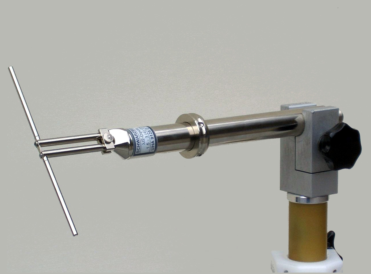
The most basic of antenna designs will be familiar to many readers as the dipole, two conductors each a quarter wavelength long arranged in a straight line with a usually coaxial feeder connected between them in the centre. It’s the antenna from which many other designs are derived, so knowing how to spot it within those other antenna designs gives you an immediate handle on how long a quarter or a half wavelendth is at that frequency. A 100 MHz antenna is therefore half of the 3 metre wavelength, or around 1.5 metres long. If you cast your eye around the rooftops until you see someone with an FM radio dipole antenna for 88 to 108 MHz then, it will be somewhere about that size.
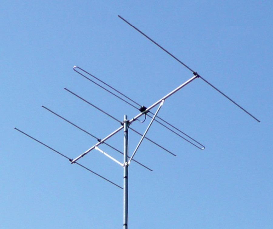
If you cast your eye around the antennas on rooftops, on utility buildings, and in other places, you’ll notice that few of them are dipoles. Many of them are long spiky affairs, a central boom with a ling of elements at right angles to it, or a triangular shaped array of elements yet again along a central boom. A rooftop TV antenna is a great example of the type, called a Yagi-Uda array after its inventors. They set out to create a wireless energy transmission system using radio waves, and found themselves instead creating a highly directional array in which a dipole was joined by a set of passive elements. The dipole is still the same though, so if you can estimate its size you can home in on the frequency.
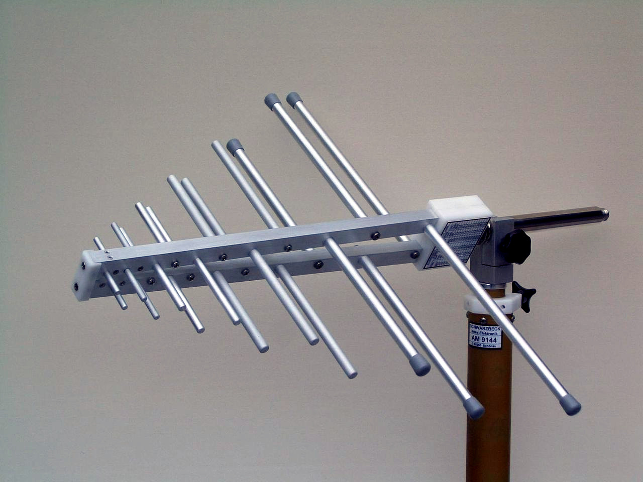
There’s another type of antenna similar to the Yagi-Uda array, which looks extremely similar except for a characteristic triangular shape. This is a wideband antenna called a log-periodic, and it’s an array of dipoles of different frequencies. Yet again if you can estimate the size of each dipole it’s possible to work out the spread of frequencies by looking at the largest and smallest ones.
Both a Yagi-Uda and a log-periodic antenna are directional, so besides working out its frequency you can also tell where the station it’s communicating with is. I once spent a mildly enjoyable summer afternoon on a motorcycle combing the lanes of Oxfordshire to find the base station for the local village water plants this way, as each of them had a Yagi at about 450 MHz on a small mast By lining them all up on the map I was able to find the control point, not particularly surprisingly it was at the sewage plant in my local small town.
There’s a final type of antenna that you’ll see a lot of on vehicles and in other places, the vertical or whip antenna. The simplest of these is a quarter-wavelength springy wire making it easy to guess the frequency, but there are several complications which can put a guess off-course. You’ll often see whip antennas with coils either at the bottom or some point half way up, these can be loading or phasing coils to change the antenna’s performance. Usually they are to help pack a larger antenna into a smaller space, which makes the overall length less useful as a guide. If there’s a secret, it’s that most amateurs have seen enough antennas by now that we recognise the difficult ones by comparison to those we’ve seen. Apologies, maybe you do need an Elmer to pass this down after all.
Header: Bert Kaufmann from Roermond, Netherlands, CC BY 2.0.


I always like telling baby engineers that antennas don’t have gain. At best they have loss but can focus the remaining power with directionality.
Also ask them to get me me a quote and vendor for an isotropic antenna.
Isn’t an antenna just a device to match the impedance of the cable to the impedance of the air? 😉
Think that’s right. Always thought the ARRL logo was trying to say, “To complete the circuit, connect one wire to the ground and the other to the sky.”
The ARRL logo represents part of the schematic diagram of a typical early receiver or transmitter. A transformer was used at the input/output, with one side going from the antenna to ground as shown in the logo. The other side of the transformer served as the input to a receiver or the output of a transmitter.
I always thought it was just nonsense, some schematic symbols that didn’t mean anything. And that goes back 51 years, to when it was the American Radio Relay League, rather than now when “ARRL” seems to mean nothing, except the name for ‘the National Association Amateur Radio”
Always thought that to connect your radio to another one, you need to hook one wire to the ground and the other to the air.
In the old days, no cable to connect the transmitter to the anttenna. Later, there was open line feeder. Coax wasn’t a ham thing until after WWII.
” no cable to connect the transmitter to the antenna”
So, they were using waveguide prior to WWII?
B^)
At the very beginning, the antenna was often connected directly to the transmitter. Some hams still do that, either by using a random wire antenna along with an internal antenna tuner in the radio, or by using a compact end-fed half wave that plugs directly in like the K6ARK antennas.
Directionality is treated as a gain in the radar range equation — that could be the source of the confusion.
Gain is an increase in output compared to a theoretical isotropic radiator. An antenna that focuses power in a given direction indeed has a “gain” compared to a perfect omnidirectional antenna. Essentially you are giving up power output in directions other than the desired one. The more directional an antenna is the more gain it will have but the tradeoff is a narrower effective beam width.
Beautiful explanation! I agree.
I gain-ed some knowledge from that explanation. I’ll definitely use it a-gain. I’ll get me coat.
After you reflect on that, give us a standing wave!
Correct! Antennas do have gain – just not physical power gain.
How about a dummy load? It’s isotropic, but it have *very* little gain.
True, but the usable bandwidth of a good dummy load is incredible!
It doesn’t have to be. ;)
You seem to have an unhealthy affection for semantics. Antennas can and do have gain over isotropic if they have directivity, and isotropic is a conceptualization for a spherical pattern, not an antenna. Your comments might seem cute to you, but they don’t add any value.
You just be lots of fun at parties.
You’re defending the guy who thinks it’s cute to pick on “baby engineers” with stuff that he doesn’t even understand himself?
Antennas do not have power gain. They may have directional ‘gain’, but that’s not a proper use of the term. The original comment about ‘baby engineers’ is well taken as someone who was once one. There are a lot of concepts that one needs disabused of early in ones career. This can be done with the (sometimes playful, sometimes a bit cruel) help of more experienced staff or it can happen by crashing a lander into a far off planet. I know which one I’d prefer.
The term “gain” (at least in ham radio circles) is taken to mean “gain over isotropic”, isotropic being the representation of a spherical pattern in free space, or in some cases it means “gain over a dipole at the same height above ground”. In the first case it is spec’d as dBi and in the second as dBd. And of course it is due to directionality, but it is still a real and valid radiated power gain in the intended direction … obviously at the expense of radiated power in other directions. Like I said, the OP was simply trying to be cute and using that cuteness to demean others.
“Antennas do not have power gain. They may have directional ‘gain’”
Yep, I have a humorous example of that power gain misconception. While in the USAF, I was a microwave and satellite communications maintenance technician. The link “engineering” section was just a few low ranking officers with, as was usual, probably no real technical expertise in the relative area. They were insisting upon a very large, roped off, ground level radiation hazard zone for a 8GHz dish elevated about eight feet above ground level and transmitting LOS at 400mW since that was not specifically exempted in the Technical Order. I handed one of them a microwave field strength meter and told them to find the hazard. They had to climb to the antenna feed horn to find one. Just before moving to another assignment at another base, I sent them through distribution an anonymous paper entitled “Solid Metallic Energy Generating Microwave Amplifier (SMEGMA)” illustrating how a series arrangement of waveguide connected microwave dishes could result in megawatts of output power.
If that’s how hams you know use the term, you might want to find a new group of hams to hang out with. Don’t use ‘power gain’ in those case. There’s plenty of other ways to say it.
You need to learn how to read. I never said that any antenna gives an overall power gain. What I did say is that a directional antenna gives a gain in radiated power in one direction at the the expense of radiated power in other directions.
That dipole in the first image looks like it would be close enough for ADS-B
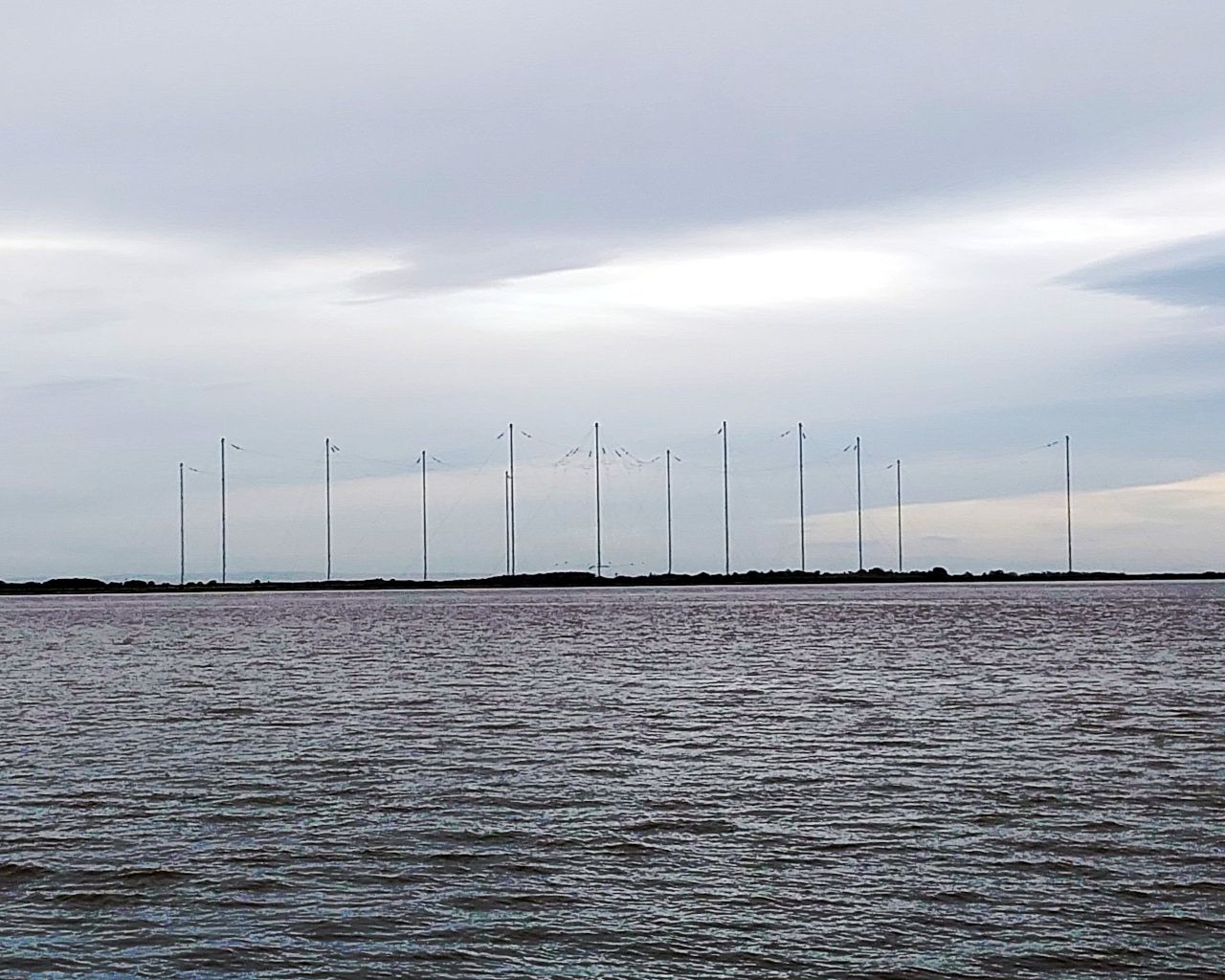
No halos, no squalos, no groundplanes, no dipoles, no sterba curtains, no collinears.
And where are all the wire antennas? End Fed Half Wave? Inverted L and V?
unless suspended between 300′ lattice masts or 3000′ long, wire antennas are for poor boomers and n00bs
You clearly know very little about antennas. Wire dipoles at a reasonable height (say 3/4 wavelength) are very efficient antennas and perform within 6 or 7 dB of much more complex arrays. In addition, it is possible to build wire arrays with considerable gain. I even built a phased pair of stacked 2-element 20 meter wire yagis suspended between two trees for Field Day one year.
Wire antennas are great for portable operation, where it is usually impractical to set up a beam. They aren’t as effective, but the antenna that you can get in the air is better than the one that you can’t.
Wire antennas are also for temporary use from buildings, which may be buildings you are visiting rather than one where you live, or for installation where something more visible like a beam on a tower would be unacceptable to the neighbors.
As David points out, you can construct very effective antennas out of wire that don’t involve 300 foot masts or 3000 feet of wire. A wire beam will work just about as well as one made of tubing (its bandwidth will be a bit narrower); the main compromise is that you won’t be able to rotate it. For his Field Day example that might not have mattered; if you live in one of the corners of the US you don’t need to, you just point your beam at the opposite corner and call it a day, the beam width of the antenna is wide enough to pick up just about everybody.
And yes, they are for people who may not want to spend thousands of dollars on ham radio. That kind of spending is not in everybody’s budget. Ham radio can be enjoyed at nearly any level of spending. A $200 station (it can be done) won’t make as many contacts or make them as easily as a $20,000 station, but many people will be happier with having the other $19,800 available for something else.
Discone
I only just discovered that while a discone can be an swr match over a very wide range, it only directs it’s power toward the horizon over one octave. Beyond that the pattern rises and breaks into lobes, just as it would for any other >=1 wavelength antenna
Then you want a di-cone.
This isn’t an antenna type textbook. It’s telling people how to guess the dimensions and thus the frequency of an antenna.
I d.idn’t mean to nitpick. But the title suggested a wide range of antennas, but the text seems to leave out some common ones.
My reference to halo wasn’t serious, they had their day but mostly faded. A Squalo was from an antenna company, Hygain, and seemed like a square halo. And not seen much since the sixties.
The halo faded because the use of horizontal polarization faded from mobile and local communication applications. Car installations now usually employ vertical polarization; depending on the band, the antenna may be a quarter wave vertical using the car as the ground plane, a half wave or 5/8 wave element with a suitable matching network, or a collinear array of multiple vertical elements separated by insulating sections. Home installations use similar but larger vertical antennas.
Horizontal polarization is still used for VHF and UHF DXing. But omnidirectional antennas like the halo are rarely used for that; Yagi-Uda antennas are the norm. A Yagi-Uda can also be used for vertical polarization if a directional pattern is desired, but that requires the use of a non-conductive support for the antenna to avoid having the mast interfere with the operation of the antenna.
“but that requires the use of a non-conductive support for the antenna to avoid having the mast interfere with the operation of the antenna.”
Interesting, I wouldn’t have thought of that!
Sixty years ago, VHF was mostly AM, CW, and a bit of SSB. Since home antennas were horizontally oriented, it made sense to use halos on cars to avoid the loss from mixed polarization.
But towards the end of the sixties, FM became the thing for local VHF. And that adapted a lot of commercial two way habits, not a surprise since it began with commercial 2-way equipment. I have no idea if vertical was adapted to get rid of those halos.
But it put all those Communicators and even Comcraft rigs on the display shelf.
And after all these years of believing it was 5/8 wavelength…..
“guessing dimensions at a difference” should be “guessing dimensions at a distance” methinks.
Those dipoles/yagis on the roofs certainly won’t be FM broadcast antennas. Nobody uses/used a huge yagi for listening to radio.
Those are analog TV antennas, these days mostly leftovers from the days past because analog TV has been mostly switched off and replaced by stuff like DVB-T2 and similar.
FM broadcast on the far left, under the UHF Yagi, the rest are UHF Yagis (prob. for TV) and there’s at least 4 satellite dishes.
Those look like VHF separates vs. the UHF mini booms that are cheaper and easier to deploy. Often aimed at different direction signal sources, no rotor needed. Till digital TV came along any full band TV antenna could do FM broadcast and was often advertised for all three bands. FM is between ch 6 and ch 7 as well as is VHF public safety band.
I DX’ed Chicago FM thru my parent’s TV antenna (120mi or 2 horizons) more than 50 years ago. Till the last few years a 10foot long Yagi sat on a wheeled pole in my upstairs living room. Chicago, Urbana, Indianapolis, no FM in Lafayette (Purdue) till 2013 as far as public radio and jazz goes. Now that high gain 10dB antenna is outdoors aimed to our NPR lpFM at 200 watts which is 8 mi away in valley terrain. Though there is the web it’s still needed.
Home FM radio to most people is a clock radio and the locals but TV gets to have a real antenna.
Nobody might have used a Yagi for FM broadcast where you live, but here where I am they’re quite common.
The sole purpose of a Yagi antenna is to listen to radio.
First time I ever saw a Yagi (that I was old enough to know it’s name) I was installing it for a Wireless ISP that used Tower based access points. It was somewhere around 900Mhz and a Yagi pointed right would get end users 2-3 miles from the tower connected, further if they had an old TV or CB tower ;)
https://www.nutsvolts.com/magazine/article/rotators
“Nobody uses/used a huge yagi for listening to radio.”
They most certainly do, but maybe not for ordinary domestic purposes.
From my link:
Medium-duty rotators can handle a single mid-sized HF Yagi or log-periodic for 14 to 30 MHz. By “mid-sized,” I mean a Yagi with a few elements on a 12 to 18 foot boom weighing 50 pounds or less. A small VHF/UHF Yagi can be stacked with the HF beam. This is a very common configuration: a three-element “tribander” (20, 15, and 10 meters) with a six-meter and two-meter Yagi above it. A few sections of Rohn 25 tower or an HDBX self-supporting tower make for a sturdy antenna system.
DXing FM broadcast is a thing.
Looks like a Channel 6 antenna or a Channel C antenna. I guess that photo was made near Turin, Italy where for historical reasons, basically an USA transmitter was used for test transmission ad was on channel 6, a 625/50 broadcast was using an NTSC frequency. Interestincgly enough some test transmission were made using NTSC color system and in Turin sometimes in the TV museum the NTSC camera is on show.
I could use one of them… VHF station within 60 miles of me has 8 (!!) subchannels, and 4 of them are good ones. (It’s classic stuffs that was only SD anyways, not HD on 8 on VHF that would be real cray cray.)
Phased array antennas (Ionica, “Squarials”, etc)
Dish antennas – for ye olde statellites (sic).
When I went to my general license class at FRRL.org they showed a video by Frank Rutter k3aw that was awesome in every respect. At the time I asked if the video was available anywhere else and was told that the club had the only copy :( However, Ifound my notes and it’s on the video site :) heres a link to the best 1:08 hours of your life. https://www.youtube.com/watch?v=LEigIMS6bo4 Enjoy!!
Thanks for the link!! :)
Great article! I’m in the phase of being a radio amateur where I can safely go into a hardware store and not have to keep asking myself “Could I make an antenna with this?”
I heard that on 10 meters once, the four yorkshiremen crappiest antenna sketch. “Wet string?! We were lucky to have string, we ‘ad to pick apart our own jumper and spit on it…”
No salt water nearby? :)
One if these days I intend to get my old aluminum crutches out of the garage and see if I can’t load them up.
You could use them as a hairpin match for a larger antenna! :)
A crutch is somewhere between a meter and a meter and a half long. (They either come in multiple sizes or are adjustable to suit the user.) A pair of 1.5 meter crutches would be just about right for a dipole for the 6 meter band. A pair of 1 meter crutches would work on the 4 meter band that some European countries have, and a single one with a suitable matching network would make a half wave antenna for the 2 meter band.
You’d need to add inductance to make a single or two crutch antenna resonate on any of our HF bands.
It is the Carmel neighborhood of Barcelona
Parabolic Disc Via digital
Dictator Franco VHS TV antenna
Yagi and 14dbTagra
Two CB antenna
Thank you for this introduction. I’m still an amateur myself, but I would recommend “Handbook of Radio and Wireless Technology” by Stan Gibilisco. The later chapters have pretty good descriptions of antenna technology, including driven elements, reflectors and parasitics.
I milled a slotted waveguide antenna for 2.4ghz wifi back in the early days (2000), it rocked:
http://www.trevormarshall.com/waveguides.htm
Northrop Grumman had an E-3 slotted waveguide antenna hanging in a large public space at their Glen Burnie, MD plant.
In the early 60s some college students scaled the antenna on a picture of a Russian satellite. By determining the frequency they could intercept it’s signal. Back then control signals were audio frequency so decoding the signals allowed them to spy on the Russian. Big deal in those cold war times
Log-periodic TV antennas are quite common. The original UHF TV band, which ranged from 470 to 890 MHZ, almost a 2:1 frequency spread, nearly required one rather than a Yagi-Uda design to provide good coverage of the entire range. It is also common to see a log-periodic design used for VHF TV, with FM reception thrown in; those cover the range from 54 to 216 MHz. a 4:1 spread. The alternative would have been two separate Yagi-Udi sections; one for the 54-88 MHz range (channels 2-6) and another for 174-216 MHz (channels 7-13).
Here is a link to one from Channel Master that is currently available: https://www.channelmaster.com/collections/tv-antennas/products/advantage-100-outdoor-tv-antenna-cm-3020 The back V-shaped section is a log-periodic array for channels 2-13 and FM radio. The smaller elements in the front, along with the corner reflector elements, are for UHF TV; they cover the range from 470 through 700 MHz. Older designs would have had a UHF section with coverage up to 900 MHz, which would be longer for any given amount of gain.
“a summer afternoon on a motorcycle combing the lanes of Oxfordshire to find the base station for the local village water plants”
Sure you were. You weren’t looking for quaint country pubs serving local ales, no, not at all.
Just joking. I can think of worse ways to spend a summer afternoon, whether looking for radio sources or pubs.
Probably just trying to work around the tailback because the Diddly Squat Farm Shop had a special on Bee Juice.
Now tell us that solar concentrates don’t have gain either, just loss.
A good friend built a omni-directional gain antenna system (yes, including elevation) for Air Force One. Yes it can be done, just think about it for a while.
Then there’s the ones that don’t exist anymore, microwave horns dotting the horizon for AT&T long distance calls,
I would guess that horizontal crossed dipoles would closely approximate a dome-shaped radiation pattern with gain over isotropic due to ground reflection.
This fascinates me. It would serve me well to actually do some reading on antennas (antennae?) since my two main hobbies are electronics and R/C vehicles. Instead, I resorted to purchasing a set of each different type (in the 2.4 & 5.8gHz range) from Amazon, then using an ESP32 to read their RSSI at the same distance. Meh. So far, the “lollipop” CP jobs have been the most effective for my purposes (video transmission), but I haven’t yet moved on to the more expensive stuff…
What about these antennas that are just a cunningly shaped PCB trace? Maybe with a little tiny SMD cap(?) for matching… Or those tiny SMDs that ARE the antenna? I would definitely read an article on those.
When I was a kid, 2G GSM on 900MHz was state of the art and mobile phones still had visible stubby little antennas. You could even solder an LED as a jumper across aome of the coils of your Nokia 5110 antenna and it would flicker when a call was coming in!