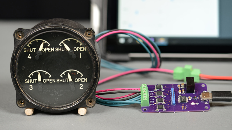
[Glen Akins] had a WW2-era aircraft engine cowl flap indicator lying around (as you do) and thought it would make a jolly fine USB-attached indicator. The model in question is a General Electric model 8DJ4PBV DC Selsyn, which was intended for four-engined aircraft. For those not familiar with the purpose [Glen] explains in his detailed writeup, that piston-engine aircraft of that era were air-cooled, and during conditions of maximum engine power — such as during take-off — flaps on the side of the engine cowling could be opened to admit additional cooling airflow. These indicator dials were connected to a sender unit on each of the flap actuators, providing the pilots an indication of the flaps’ positions.
The mode of operation in the DC power environment of WW2-era aircraft utilised the concept of variable magnetic field orientation. The sender is a potentiometer, sending a voltage down the wire between 24V and ground. The indicator unit has a pair of coils set at 120 degrees around a ring, with the coils wired in series, and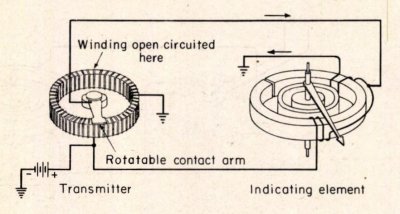 the center tap connected to the sender signal. The other ends of each coil connect to the DC power bus so that as the signal voltage varies, the coils produce a varying magnetic field. Lower voltages bias the field towards the coil connected to 24V, and higher voltages the other way. A permanent magnet in the center is attached to the indicator dial, with a small spring to bias it to the center. A very simple but effective arrangement, giving analog feedback of the actual flap position.
To interface this thing to modern technology, a custom PCB was constructed leveraging the USB functionality of the PIC16F1459 microcontroller, that [Glen] was already familiar with. Four Microchip MCP31HV41-502 digital potentiometers were pressed into service directly driving the coils of the indicator units. That might seem like an odd if not viable way to drive such a thing, but [Glen] goes into some extensive theory and some modeling to determine which devices would have sufficient margin, which is worth a read for the unfamiliar. After bit-banging the SPI connection to the digipots (even though the PIC has hardware SPI) [Glen] goes on to describe how the USB endpoints work, finishing off with a .NET application to drive it all.
We’ve seen plenty of hacks bringing retro hardware back to life, connecting to modern computing. Here’s a project that goes the other way, building custom aircraft instrumentation from modern parts.


Typo in the blog post and this article: The pots are called MCP41HV31 (4 and then 3).
https://www.microchip.com/en-us/product/MCP41HV31
Thanks. Fixed. Got it right 10 out of 11 places. I wrote the first paragraph last so I was pretty tired by that point. Lol.
I absolutely love this. It ticks all my boxes:
– fusion of vintage old tech with new tech without destroying anything
– elegant and beautiful custom made interface
– superb write-up with in-depth tech discussion
– an all-round fun hack!
It’s just great. Synchros are an interesting device, Hackaday’s Al Williams had a great article on here about them a few years ago (definitely recommend browsing the US Navy Synchros doc OP 1303 referred within):
https://hackaday.com/2018/04/25/retrotechtacular-synchros-go-to-war-and-peace/
Thanks! I try not to permanently alter anything. Use external connectors as much as I can, look for internal connectors I can tap into, etc. I’m working on some AC synchro stuff too but it’s taking a back burner to getting the next DC Selsyn blog post written.
Absolutely agreed! I’ve looked at doing something similar to monitor my servers. Maybe I should actually do that and get on here :)
oh man, I remember trying to drive similar cowl flap indicators like 10+ years ago and failing miserably. Super excited to give this a try, thanks for the great writeup!
No problem! I’m working on a write up on three wire DC Selsyn’s. They require programmable constant current sources though to keep from frying the internal windings. The hardware and software are done. It’s writing, photos, and video time!
Very nice!
Did something really similar to revive an old car rpm meter that was using a galvanometer under the hood. The technique involved was a bit different as it was more like a single npn transistor commuting the galvanometer line with the adequate PWM.
This was controlled by an attiny 88 connected to the car’s magneto contact points with proper voltage conditioning before entering the chip.
Worked nice as well, mapping was almost 100% linear, thus rpm of the engine was really close to a 1:1 match with the rpm dial.
Nice write-up congrats. Must have taken some time!
Do you have any experience driving 400Hz Synchros? Smart solutions?
I have restored a F-111F cockpit including cabling & connectors, basic electrics working.
Now want to drive the instruments many have Synchro or resolver 400Hz interface. Some indictors simple torque synchros.
Working to connect to MSFS!