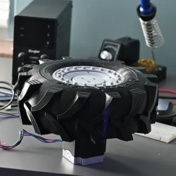
When [Michael Rechtin] learned about Radial Vector Reducers, the underlying research math made his head spin, albeit very slowly. Realizing that it’s essentially a cycloidal drive meshed with a planetary gear set, he got to work in CAD and, in seemingly no time, had a design to test. You can see the full results of his experiment in the video below the break. Or head on out to Thingiverse to download the model directly.
[Michael] explains that while there are elements of a cycloidal drive, itself a wonderfully clever gear reduction mechanism, the radial vector reducer actually has more bearing surfaces, and should be more durable as a result. Two cycloidal disks are driven by a planetary gear reduction for an even greater reduction, but they don’t even spin, they just cycle in a way that drives the outer shell, setting them further apart from standard cycloidal drives.
How would this 3D printed contraption hold up? To test this, [Michael] built a test jig with a NEMA 23 stepper providing the torque, and an absurd monster truck/front loader wheel — also printed — to provide traction in the grass and leaves of his back yard. He let it drive around its tether for nearly two weeks before disassembling it to check for wear. How’d it look? You’ll have to check the video to find out.
If you aren’t familiar with cycloidal drives, check out this fantastic explanation we featured. As for planetary drives, what better way to demonstrate it than by an ornamental planetary gear clock!


I’m happy to see this.
This type of gearbox is indeed an improvement of the cycloidal. I never liked the loose planet pins in the big holes in the cycloidal drives, and this mod eliminates that. This type is being manufactured commercially by Nabtesco. Nabtesco is a quite big manufacturer of gearboxes for industrial robots.
An obvious way of improvement would be to mill the thing out of some decent quality steel, but that is not practical for most hobbyists (Youtuber .AndysMachines has some nice video’s for making the machines to mill gears).
Another improvement that is easy to do is to make the inside of the hub of centerless ground steel pins. These are a commodity product and quite cheap. This probably also improves efficiency because the pins can turn. They will probably roll over the outside of the cycloidal disks ( which reduces wear on those), and then slide in their support which has a much bigger surface area.
Those pins could even be a bit longer, and then supported by needle bearings. Needle bearings such as for example BK0810 has one end closed, so the steel pins don’t fall out, and they are quite affordable. A bag of 50 of them costs EUR23 on Ali.
Like all planetary-alternative gear reducers, there are tradeoffs. By my understanding, it’s possible to get at or near zero-backlash with a cycloidal. I have never designed for one, but I imagine why it’s feasible to get there with cycloidals but not gears is because the machining tolerances are easier to match in a one-setup milling ops for the cam follower plates and bearing plates. You’d need extremely tight tolerances to be able to achieve the static preload between the cams and the follower plate necessary for zero backlash, but some suppliers claim to have the capability.
This gearbox reintroduces the backlash from gearing. That’s not a disqualifying trait, but it’s definitely a tradeoff. On the plus side, like you noted, no cantilevered pins on the output flange and the possibility for more gear reduction in a small space.
>You’d need extremely tight tolerances
Or a slightly conical shape with a spring load to take up the slack.
The gears are before the cycloidal. That means if the cycloidal has a 20:1 gear ratio, the backlash introduced by the gear tooth is also reduced by a factor of 20, and that means it’s not a big factor. Gears do need a bit of backlash because of their partially sliding friction, but the cycloidal can have rolling resistance only and this makes it possible to add a preload in the cycloidal disk, and this can be balanced with the stiffness of the gearbox housing. Especially with 3D printed plastic.
Part of the accuracy of cycloidal drives is probably also because of averaging of manufacturing tolerances over the many pins
Planetary Gearing*
*orbits not included
Indeed. A gear surrounded by a few gears does not a planetary system make.
What approximate gear reduction rate did this achieve?
There’s no information about the mathematical choices on this design. So you can’t know. I guess the easiest way to estimate it is to count the number of pins on the output shaft and the number of “teeth” on the cycloid plates. If there are 15 teeth, and 16 pins, it’s 15:1 reduction ratio, to be multiplied by the internal sun/planet gear ratio.
From 1:48 in the video, ~1.7:1 for the spur gear reduction and 20:1 for the cycloidal, Total of ~34:1
Just curious. Is the rotation smooth or is it “intermittent” in a reduced scale kind of way?
The rotation should be smooth.
If I understand correctly, these type of reduction are good at high speed for the input shaft. But when going low speed, you’ll get wobbling and oscillations on the output shaft since the output pins on the cycloid plate won’t be driven by their momentum but also by the opposite momentum/resistance of the output shaft and thus will force the plates to counter-rotate to adjust.
That’s the usual issue with any device that can be operated in reverse, even if no backlash, you’ll still get a frequency of operation where it breaks or fails to match expectations.
This design will also have backlash, as a portion of it is a traditional planetary gearset.
Yes, you can see the stuttering in the video as well.
Haas uses a cycloidal drive for their B and C axis for their UMC 5 axis machines. I would be very surprised if they had any wobble as that machine should hold tenths (.0001″) and more.