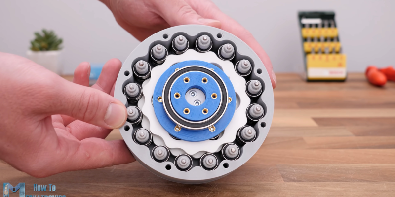
A cycloidal gear drive is one of the most mesmerizing reduction gears to watch when it is running, but it’s not all just eye-candy. Cycloidals give decent gearing, are relatively compact and back-drivable, and have low backlash and high efficiency. You probably want one in the shoulder of your robot arm, for instance.
But designing and building one isn’t exactly straightforward. Thanks, then, to [How To Mechatronics] for the lovely explanation of how it works in detail, and a nice walkthrough of designing and building a cycloidal gear reducer out of 3D printed parts and a ton of bearings. If you just want to watch it go, check out the video embedded below.
The video is partly an ad for SolidWorks, and spends a lot of time on the mechanics of designing the parts for 3D printing using that software. Still, if you’re using any other graphical CAD tool, you should be able to translate what you learned.
It’s amazing that 3D printing has made sophisticated gearbox designs like this possible to fabricate at home. This stuff used to be confined to the high-end machine shops of fancy robotics firms, and now you can make one yourself this weekend. Not exotic or unreliable enough for you? Well, then, buy yourself some flexible filament and step on up to the strain wave, aka “harmonic drive”, gearbox.
Thanks to serial tipster [Keith] for the tip!


>The video is partly an ad for SolidWorks
Thanks for mentioning it, I think I’ll pass on watching the video then.
When I was looking into cycloidal gearboxes, I found a parametric python script that generated the curve disc directly in G-code. I opened it in bCNC and exported it as .DWG, which I could open and further process in FreeCAD.
That was some time ago though.
If you start with the link below, you probably find something similar quickly.
https://html.duckduckgo.com/html?q=cycloidal+gear+generator
One of the very attractive points not mentioned is that cycloidal gears are relatively easy to make with modest tools.
The key to higher gear ratio’s is to use thinner pins, but because the pins roll over the circumference of the curve disk you really do want these pins to have bearings.
to satisfy both these, you can buy cheap hardened steel 8mm pins, and combine them with HK0808 bearings. The idea is that the disks roll over the 8mm pins, and the HK0808 bearings are pressed into some 3D printed plastic or CNC milled wood or other. For this the pins need to be longer of course, about the length of both disks plus the height of 2 of those bearings.
I’ve been thinking about designing and making a goodcycloidal gearbox in this way, but have not gotten around to work out the details.
Also have a look at Nabtesco. They make loads of these gearboxes, and they use a slightly different approach. They combine the cycloidal gear with a planetary gear. They can have a hollow shaft, because they use three excentric cam shafts in the “planet” positions.
video from Nabtesco
https://youtu.be/dmWkLOAvKkw
The title of this article is idiotic! EVERYONE WILL ALWAYS NEED A CYCLOIDAL DRIVE! :)
> This stuff used to be confined to the high-end machine shops
at least the idea is no longer intangible. Perhaps it can be read as a memo that our DIY wire EDM community is still too small, otherwise we’d be seeing skew gear tutorials and the likes (BAXEDM?) :)
No
If made from silver, could it be colloidal cycloidal?
B^)
Nice to see this from my eng days mid 1970’s as was touched on in engineering drawing classes – pre cad, A2 paper, indian ink, eek !
First saw a “hyper” cycloidal pawl configured type drive in a patent some time in mid 1980’s by an Australian politician. It had an on the go adjustable pawl arrangement so was continuously variable within reasonable range close enough to that needed for a typical car – yet was quite a bit shorter than a conventional manual or automatic transmission, I recall it had some (minor) vibration & wear issues at high speeds. The video reminded me of it, so thanks for posting this :-)
Curious on the one or general types in the video – any issues with vibrational harmonics (longitudinal as well) in large fast rotating machinery ?
It occurs to consider the existing and rapidly looming state of the art in respect of automated design methodology eg design feedbacks mapping primitives on permutation spaces dynamics…
These days with advanced genetic algorithms in mechanical dynamics design one wonders if an appropriate program could reach some design best fit asymptote of the limit ie combination of cost efficiency variable range mass size robustness power – then spit out a set of 3D print files to make the components & explore it, even as a uni student project :D
If the disks are correctly made, (an offset epicycloidal curve) and the eccentricity of the central drive is proper, there is only rolling contact between the disks and the housing or outside pins. No need for all those bearings around the perimeter (the pins are fixed circular cylinders).
The shape of the disk can be made graphically (I have done it in Inkscape -tedious but you do get an .SVG directly) or mathematically