Hackers frequently find themselves reverse-engineering or interfacing to existing hardware and devices, and when that interface needs to be a physical one, it really pays to be able to take accurate measurements.
This is easy to do when an object is big enough to fit inside calipers, or at least straight enough to be laid against a ruler. But what does one do when things are complex shapes, or especially small? That’s where [Cameron]’s DIY digital optical comparator comes in, and unlike commercial units it’s entirely within the reach (and budget) of a clever hacker.
The Comparatron is based off a CNC pen plotter, but instead of a pen, it has a USB microscope attached with the help of a 3D-printed fixture. Serving as a background is an LED-illuminated panel, the kind useful for tracing. The physical build instructions are here, but the image should give most mechanically-minded folks a pretty clear idea of how it fits together.


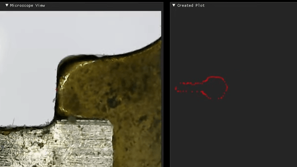
So how does it work? One places the object to be measured onto the illuminated bed, and the software shows a live microscope view, with a tiny cross-hair in the middle of the video. By jogging the microscope around — which the platform is capable of doing in increments as small as 0.1 mm — one can visually mark a series of points on the object, creating a sort of point cloud.
Because the distances between these points are recorded by physically moving the microscope in known, real-world amounts, the resulting “point cloud” accurately reflects real-world points on the actual object. From there, one simply exports as a DXF, then imports into the CAD software of one’s choice. The last step is essentially connecting the dots. It requires some patience from the operator, but it’s highly accurate, and the price is certainly right.
The popularity of 3D printers has helped make CNC hardware cheaply accessible to hobbyists, and their precision makes them attractive foundations for projects that measure small distances. You can see [Cameron]’s Comparatron in action in the video below.


One does not simply export as a DXF.
Why not, it is just a text file and the part for describing points/polylines is fairly trivial to implement.
Know your meme. One does not simply walk into Mordor.
I was surprised how easy it was to do! There are a couple of Python libraries that handle the nitty-gritty details, so all you have to do is define the workspace, a layer, and the objects (points in this case).
But what sort of dxf. It seems every program that can export them exports a slightly diferent type of dxf, and every program which imports them (particularly laser cutting software) only seems to recognise a subset of all the possble different dxf “standards” that various programs export.
I’d rather buy LPL’s Genesis Set and just pick the lock. Most locks are picked within few minutes so it’s cheaper than buying microscope, rails and sedes motors.
Haha, the key was just a demonstration. It’s useful for far more than that (and there easier ways to replicate keys).
Say what you want man. It’s still hardly useful because of camera aperture distrotion.
If you need accurate measurements use document scanner.
I don’t think that there is any issue with aperture distortion. In the video it is clear that there are discrete measurements being made at the same sight line through the lens for each measurement (the little dot). If there was image capture over the field, I’d agree with you.
Because the camera moves and the crosshair is always in the same place in the visual field, the quality of the lens shouldn’t matter.
The accuracy here is only limited to the steps of his gantry axes. That being said, unless he can magnify, and be more granular than a flat bed scanner, I think I would find the former more expedient. B/W high contrast scan, apply edge detection, subtract interior, limit adjacent matching color pixels to two on your line color, and no fiddling around with placing points. Of course that only works with more or less flat surfaces. The screw he’s scanning on the project page would be more accurate on his setup, or imaged from a very long focused camera.
Please stop using “my” username, and come up with an original one (i.e. do not use someone else’s either).
No lol
But I like using ATmegas, what can I do?
Distortion will never matter for a point in the centre of the camera’s field of view. By moving the camera to kep the centre on the points of interest, rather than finding those points within a static image you avoid all lens distortion effects. A light ray going in to the middle of your optics always just goes straight through.
Increments as small as 0.1mm ? Isn’t that a bit big for “tiny objects”?
That said, the idea seems sound enough. Folk have been using probes on CNC machines to digitise shapes for a while, and using cameras to align to features. This is just putting the two together.
Here is a video of the former, I think it is worth posting here because the G-code that traces the outline is in the description. (it’s a “keep turning right” algorithm)
https://youtu.be/JO8lLaV6pbw
I doubt it would copy a laser cut car key.
Looks to be built on a laser cutter frame with belt drive. Going to need a restart to get better.
Not supposed to be a CMM, rather a scanner for 3d printing, so no point being more accurate.
Nice. The expensive ones probably are telecentric, so they can accurately measure across most (or all) of the visual field with minimal focus adjustment.
Hmmm… pick up a low cost (~100 used, MML2-ST65D) 2x telecentric. Add to a PI HQ camera (kings ransom time). You’d only get a visual field of about 4mm diagonal, but you’d get theoretical resolution of 5.8um (~0.75um for pixel pitch, but the optic spec says 5.8) across the face with no parallax. A little machine vision and machine control could step across the entire field and rapidly capture and reconstruct an accurate scan of an object. Depth of field of 0.35mm and a working distance of 65mm for the mentioned part.
I wonder if that would be more a step forward or backward for this setup.
I wonder how accurate/precise 3D printer motion axes are – would one of those parts-only Enders on eBay be a usable starting point? I suspect not if you needed high precision, but maybe good enough for basic home-shop usage(?)
Basic leadscrew actuators are still pretty cheap, and would probably be good to +/- 0.05-0.02 mm over short distances, provided you made sure you were always measuring coming from the same direction to avoid backlash.
How does this improve of simply taking a picture and using that?
Put it on a paper with calibration dots, take a snap, and Bob’s you uncle.
Can’t you just use a document scanner?