In our previous article on Ball Grid Arrays (BGAs), we explored how to design circuit boards and how to route the signals coming out of a BGA package. But designing a board is one thing – soldering those chips onto the board is quite another. If you’ve got some experience with SMD soldering, you’ll find that any SOIC, TQFP or even QFN package can be soldered with a fine-tipped iron and a bit of practice. Not so for BGAs: we’ll need to bring out some specialized tools to solder them correctly. Today, we’ll explore how to get those chips on our board, and how to take them off again, without spending a fortune on equipment.
Tools of the Trade
For large-scale production, whether for BGA-based designs or any other kind of SMD work, reflow ovens are the tool of choice. While you can buy reflow ovens small enough to place in your workshop (or even build them yourself), they will always take up quite a bit of space. Reflow ovens are great for small-scale series production, but not so much for repairs or rework.
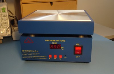
A smaller, cheaper and arguably more versatile tool is a hot plate. Although you can convert cooking appliances into soldering hot plates, it’s more convenient to buy one specifically made for the purpose with an adjustable temperature controller. Also known as “pre-heaters”, these can be had for less than $100 from the usual online channels. They’re pretty easy to use, too: simply place your board on top, set the desired temperature and wait for the solder to work its magic.
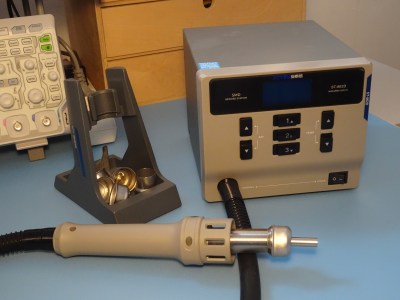
A drawback of hot plates is the fact that they heat up the entire board at once, making them less than ideal if you want to solder or desolder a single component. For that, a hot-air soldering station is the tool to use. Professional hot-air stations can run into thousands of dollars, but you can buy lower-range models, with adjustable temperature and airflow, for between $100 and $300.
Hot plates and hot-air soldering stations also work together very well: the hot plate can be used to pre-heat the entire board to about 150 °C, with the hot air gun used on just the part to be soldered. This reduces thermal stress on the board compared to heating up just one spot all the way from room temperature.
If you’re starting from scratch and are wondering what tool to buy for your first BGA project, here’s our advice: as a bare minimum, buy a hot plate; if you can spend a little more, get a hot-air soldering station; and if you want the best possible toolset, buy both.
Soldering – Get that stencil ready
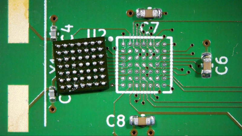
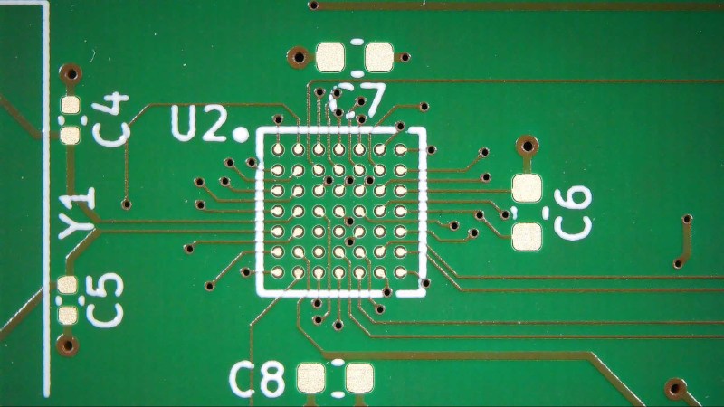
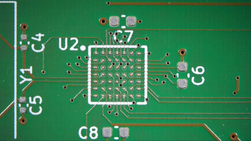
No matter whether you use an oven, a hot plate, a hot-air station or any combination of those tools, the basic steps for soldering BGA chips are the same. Let’s start from the bare footprint for the 49-ball ATmega164 that we designed last time:
The first step is to deposit solder paste using an SMD stencil. Most PCB manufacturers nowadays offer the option to order a stencil along with your boards, and this is convenient if you use solder paste for any SMD components, not just for BGA parts. Align the stencil with your board (a jig comes in handy here), then spread a bit of solder paste across the required area using a squeegee. You should end up with a nice, even layer of paste across all pads.
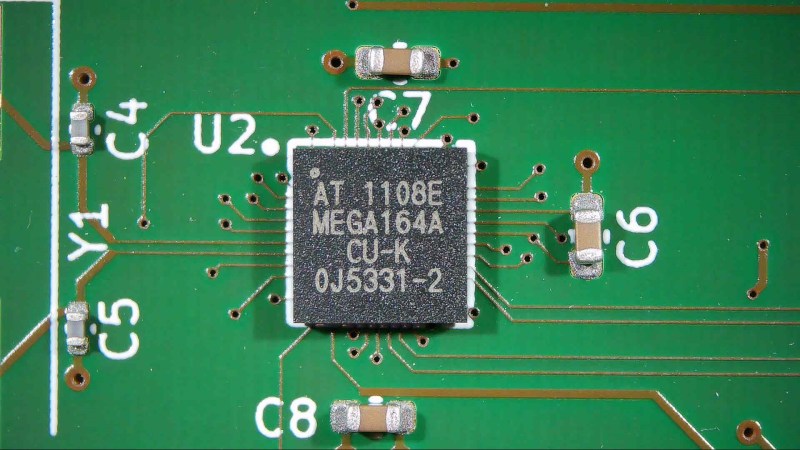
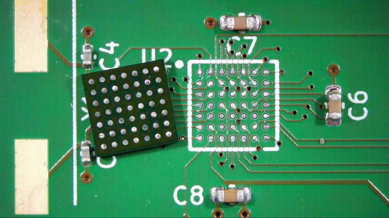
Next, we’ll place the components. You can use tweezers or a vacuum pickup tool, or even a complete pick-and-place machine if you’ve got one. Note that for the BGA chip you can’t see the pads when placing the component, so having the package outline on the silkscreen helps a lot with getting a proper alignment.
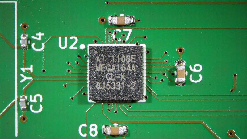
Finally, we’ll heat the board to let the solder reflow. If you’re using an oven, simply set it to the reflow profile recommended in the chip manufacturer’s datasheet. When using a hot plate, set it to the peak temperature needed: typically about 245 °C for lead-free solder. You might want to set it a few degrees higher to account for any temperature gradient between the bottom and top of the board.
As the board heats up, the BGA chip will move a little bit as surface tension aligns the chip with its footprint, but typically it’s hard to see whether the solder has properly melted everywhere. It’s convenient to place a few resistors or capacitors on the board even if you were planning to reflow only the chip, because you can easily tell from those components whether the solder has reflowed properly.
If you’re using a hot-air station, you’ll need to experiment a bit with its settings to find what works best. Especially the “flow” setting can vary quite a bit between models, so you’ll have to figure out how much airflow can be used without blowing the components all over the place. Once you’ve found the proper setting, apply the heat evenly across the chip and its immediate surroundings. When the solder balls melt, you should see the chip wiggle its way onto its footprint.
The stencil-and-paste method method is the preferred way of soldering BGAs, and is typically the method recommended in manufacturers’ datasheets. But it’s still possible to solder a chip without a stencil – sometimes you don’t even have a choice, such as when you’re replacing a chip on an existing board.
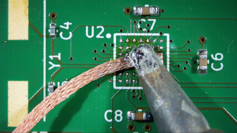
While it is possible to directly solder a BGA chip to a set of bare copper PCB pads, you’ll get better results if you apply solder to the pads first: this will ensure a solder-to-solder connection between the chip and the board, easing heat transfer. You can simply drag a blob of solder across the pads, then remove it again using desoldering braid, so that all pads are nice and flat afterwards. Make sure not to set your iron too hot, and to always dab, not drag the braid across the pads. It’s very easy to pull pads off the board if you push a hot iron down too hard.
When you’re done with the desoldering braid, clean the area using isopropyl alcohol or flux remover, then apply a thin layer of fresh flux. It’s important not to use too much, because you don’t want it to bubble and dislodge the solder balls as you turn up the heat. Other than that, you can simply reflow the board as described before.
Rework – Getting the chip off again
Even if you’ve managed to solder your chip correctly the first time, you might need to remove it again at some later point. Although you can also do this with just a hot plate, a hot air station is really the best tool for this job. If you’re working with a large board that can sink a lot of heat, preheating the whole thing makes your life much easier – without a pre-heater you’ll spend ages trying to heat the entire board by blasting at one chip.
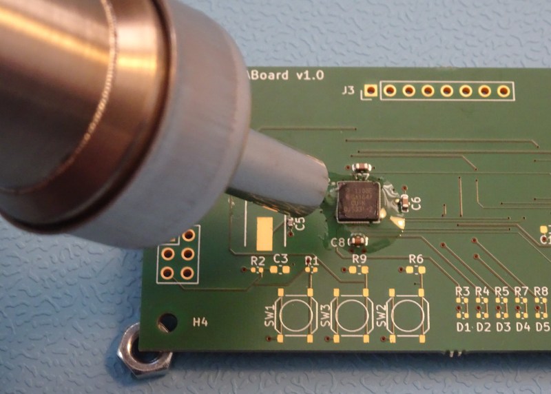
Our board is pretty small and light, so we’ll just use the hot air gun. Note how we’ve lifted the board off the table by putting small objects under the corners: this prevents the table from acting as a heat sink. Apply a generous amount of gel-type flux around the chip, then use the hot air gun to heat it up.
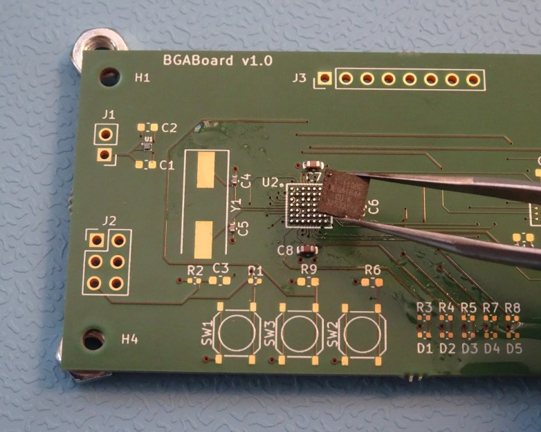
As you wield the nozzle, gently tug at the chip with your tweezers. You should be able to feel when the solder balls melt, at which point you should be able to lift up the chip effortlessly. Don’t use force at any time – if one or two balls haven’t melted yet, you might rip their pads off the board.
Once the chip is off, use desoldering braid and your iron to clean any remaining solder off the pads, then clean the area using flux remover. If your purpose was to place a fresh chip on the board, simply apply a fresh layer of flux and solder the new chip in place.
Things become more interesting if we want to re-use the chip as well: in that case, we’ll need to look at reballing.
Reballing – Ready for the next round
A desoldered BGA can be equipped with a fresh set of solder balls in a process known as reballing. For that, we’ll need a special tool called a reballing jig. This consists of a fixture to hold the chip as well a stencil that helps to position the solder balls. You can buy convenient kits that contain the jig, a set of commonly used stencils, a supply of solder balls and a few hand tools that might come in useful. A complete set like that will cost about $100.
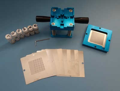
The reballing kit in our workshop came with a set of generic stencils: they differ in ball size and pitch, but have all holes placed in a regular, square grid. The idea is that you use tape to mask off the holes that you don’t need, thereby customizing the stencil to your particular chip. This works fine as long as the ball pattern on your chip isn’t too complex.
For chips with irregular ball patterns, like many memory chips, you can buy specialized stencils that exactly match those specific layouts. These are usually sold in sets that match all chips in a specific model of smartphone or tablet. Such a set is great if you’re running a repair business, but for general work a simple square set is usually sufficient.
In order to reball our chip, we’ll first clean off all remains of the old balls, just as we did on the PCB. Use desoldering braid, then clean off all remaining flux and other dirt using isopropyl alcohol or flux remover. The pads on the bottom of the chip should look flat and shiny.
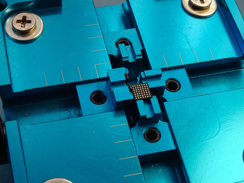
Next, we’ll mount the chip in our reballing jig. This particular model was designed for chips significantly larger than our tiny microcontroller, but we can still make it work by using only three of the four clamps. Note how the clamp on the left has a little leaf spring: we’ll position this one last, in order to put the chip under spring tension and keep it firmly in place.
Now we’ll apply a thin layer of sticky flux onto the chip’s surface, which will keep the balls in place and help them to reflow in the next step. It’s even more important here to ensure that you end up with a very thin layer, because we’ll be placing the stencil very close to the chip. If any flux ends up on the stencil, you’ll end up with solder balls stuck to the stencil rather than the chip.
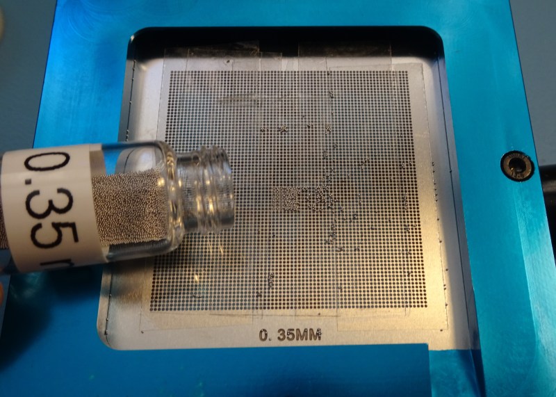
Place the correct stencil inside the top part of the jig, then align it until the holes in the stencil line up exactly with the pads on the chip. Next, take some sticky tape and close off all holes that are not needed. For our little 7×7 BGA, that means taping off almost the entire stencil. Reballing kits often come with a roll of Kapton tape for this purpose, which works great, but regular Scotch tape you find in any desk drawer will do just fine, too – there’s no need for it to be heat-resistant.
Once you’re done taping, place the stencil holder back on top of the jig and pour some balls onto the stencil.
Wiggle the fixture around to ensure there’s a ball at each position on the chip. You might need to maneuver a few stubborn ones using tweezers or a fine brush. Once all slots are filled, lift up the stencil and pour any leftover balls back into the bottle using the little ramp on the bottom right of the stencil frame.
Next, we’ll need to reflow the balls onto the chip. Hot air is the easiest method here, but make sure to use a very low flow setting: solder balls weigh almost nothing and will fly away at the gentlest breeze. Alternatively, you can carefully lift up the chip with your tweezers and place it on a hot plate or in your reflow oven. In any case, once the balls reach their melting temperature you’ll see them reposition themselves and stick firmly to the pads. After the chip has cooled off, it’s ready to be mounted on a board again.
As you can see, soldering and desoldering BGAs is not that hard, as long as you’ve got the right tools. You can get even an absolute minimum toolset – a hot plate, SMD stencil and solder paste – for less than $100. This should be enough if you just need to solder the occasional BGA chip and prefer do the rest by hand.
Of course, if you were already using a stencil and solder paste to reflow your SMD boards, then throwing a BGA chip into the mix doesn’t really change the process. And if you weren’t convinced of the merits of solder paste, now might be a good time to order that stencil and try your hand at reflowing – it’s actually a very straightforward process. Now that proper SMD soldering tools are affordable even for a modest home lab, there’s really no reason not to use them.



Nice work
Missed opportunity to name the article “Playing with balls” instead of “Working with BGAs”
Haha bravo!
Malo si se i ti ulijenio sa svojim projektima vrijednim pojave na Hackaday! Cekamo te da se pojavis ovde!
“Don’t be afraid of working with Balls, here’s some tips!”, “This really heats up my balls…and yours!”, “self positioning, fantastically shiny balls”. The possibilities are endless :P
If you are designing your own board, consider putting corner markers on copper layer instead of on the silkscreen. The silkscreen alignment can be off by enough to disturb 0.5 mm pitch BGA placement. For solder mask defined pads, the soldermask layer would be a good choice.
“…reflow the balls onto the chip. Hot air is the easiest… solder balls weigh almost nothing and will fly away… Alternatively, you can carefully lift up the chip with your tweezers and place it on a hot plate or in your reflow oven.”
Hmmm… this part sounds difficult to me. (Though I have no experience trying). I’m wondering… if you only have one chip to do or have all sorts of time on your hands to keep waiting for it to cool off… could you just put the whole jig, chip and all in the oven?
Yes, you can do this. A programmable reflow oven would be best to limit the time at temperature but a normal oven would work, it might just be tricky to operate without errors
I work at a professional manufacturing facility in Fargo, ND. I have been reballing chips and taught others how to do it for five years now. I can place and heat up to 60 to 70 solder balls at a time on large BGA chips. It takes practice but you can learn when you need to. Getting the right tools is part of it but patience is more a part of learning. I routinely work with .2 to .76 mm diameter balls and have an easy time now with even the smallest lowest pitch chips. I use simple tools, like double stick kapton tape on an old small pcb to hold the chip, a small thin probe and flux, I like the Chip Quik water based flux. Simply place a drop of the flux near your chip and use the tip of the pick to dot the pads of the chip, only a small amount of flux is needed. Then pick up some solder balls with the pick and plce them on the pads, the flux will hold some and other will stay on the pic, push around the balls until you have one per pad, wipe off the pick to make the balls stick to the pads with the flux and not the pick. Then slowly heat at low temps getting closer with air nozzle until the chip and solder gets hot enough to melt solder balls.
Thank you, Robin.
That was very informative. It looks quite fiddly but your explanation makes it sound a lot more straightforward and the step-by-step style will be handy as a reference should I want to try this.
You can also solder them as if they were LGA packages. Just force (with a toothpick or similar) the chip down onto the untinned board while solder is liquid and the excess solder will shoot out the side. Probably not good for thermal cycling performance but a quick hack to get a prototype going without a stencil, reballing setup, or the risk of tearing off pads trying to tin them.
Are you talking about doing this for reusing a de-balled BGA? Sounds good enough for a hobbyist reusing a BGA from a dev board, interesting technique.
Some chips you get from manufacturers are unballed, if your doing rework as a technician you may find yourself balling chips just to get your work done.
Might work for the likes of QFN where all the underside pads are at the edges, but for a BGA you have connections in the centre, when excess solder shoots out from the side some from the centre will shoot out only part way, you’ll get loads of shorts between the underside points when the solder cools. If only the pitching was much bigger one could have a via for every point and then blue-tack the chip to the PCB, turn it upside down, inject solder paste down each via then heat it.
I’ve done this on an 80 pad 0.4mm wlcsp after accidentally blowing the chip out of alignment with too much airflow. Worked great. Push hard enough to where it all shoots out the side.
This is a great guide!
Having done this for production/prototyping work on really weird BGAs, I’d like to add that having the right flux for your process is going to make or break any reflow or removal.
I’ve found that Chipquik SMD4300TF10 works well in most applications.
You want about half a puddle. Too much and you’ll have to vaporize a bunch before the part heats. Too little and the solder is not going to melt evenly or cleanly.
Caveats: Don’t use flux with solder paste! It already has flux!
Oh I’ll also add that you can reball a BGA by just hand soldering the pads and adding a liberal amount of flux during the process.
Can you? Yes. Should you? No.
;)
“As you can see, soldering and desoldering BGAs is not that hard..”
I don’t see. I’m still scared to death at trying this..!
Why be scared?
Disclaimer, I haven’t done this… yet.
My thought is… the next time something is being thrown out that has a BGA chip, go for it.
Practice on trash and there is nothing to fear!
Find a shop lacally that does phone and PC repair at this kind of level, ask for scraps of motherboards and cell phone boards. If they do rework they will probably have bunches. I worked at a cell phone shop before becoming a tech and we had heaps of stuff lying aroud for me to practice on.
This looks easy on a board with plenty of room to work and nothing on the back side. SMD components are not always glued to the board, so what’s the process if there’s nearby components or the back side of the board is populated? How do you keep other components from moving?
Mask with Kapton tape around the IC and on bottom side. Pre-heat to e.g. 150C with IR preheater.
Using hot air to add just enough delta-T locally on the IC to reflow it (and hopefully nothing else).
Foil tape works a fair amount better than Kapton. For a more “professional” approach there are “heat shield kits” you can get (e.g. from CircuitMedic) with a variety of solutions.
Don’t waste your money on professional heat shields, use scrap aluminum or whatever you have handy. The flux, solder tweezers etc cost enough so saving money on something your blasting with heat is worth it in the long run. I work in a manufacturing facility with an SMT line and we have products that use stainless steel and aluminum shields which have rejected parts on occasion at incoming inspection, grab these parts and use them.
The light tinning method is how I repaired a broken GeForce 6200 card. After desoldering the bad RAM chips with a hot air station and sourcing equivalent chips from Mouser, I used desoldering braid and flux to get the pads down to just flat tinned. Then I cleaned the board and applied flux, positioned the chips, then heated them with the hot air station until a slight nudge would make them spring back with surface tension. Fixed the card right up.
I have succesfully removed badly soldered BGAs with 216 balls with 0.8 or 0.65 mm pitch (ST microcontroller), added solder by running a molten ball of solder over both PCB and the BGA, then applying flux and soldered back using hot air with preheat.
These boards worked for at least a year as prototypes before being replaced by new version.
For a prototype, these ugly methods can save a huge amount of time – I spent maybe 5 minutes with each board.
BGA technology was invented by an engineer who died before the EU unwisely mandated non-lead solder in computer equipment. Unlike CPUs, GPUs have rapid hot/cold cycles which in theory shouldn’t matter, except that the manufacture of solder balls frequently results in balls with voids in them. Lead is highly ductile and so this thermal cycling doesn’t matter if there’s a void, but non-lead tin alloys are brittle and behave more like glass; after about 3 years of daily use, balls with voids eventually crack, breaking the solder joints. Some tried to solve this with heat guns but inevitably the joints would break again, often during the winter.
This is why all those MacBook Pros with discrete GPUs from the 2010s failed, leading to a class-action suit. it also accounts for the Xbox Red Ring of Death, an equivalent PlayStation failure and another associated with HP Lifebook laptops, all from the same era. Apple was charging $600 to replace mainboards with equally deficient components that eventually suffered the same fate, while repair companies were only charging $200 to reball the GPUs with lead.
Shortly after *someone* posted the industry whitepaper on solder ball manufacture to Slashdot proving this was a known issue with non-lead solder, Apple settled out of court, extended their warranty program and refunded every customer they’d charged for board swaps.
BGA is a necessary tech because the shorter the distance between the die and the mainboard, the faster the chip response is, but it depends 100% on material reliability of the solder joints.
I don’t know whether the EU relaxed their restrictions on lead or a more durable non-lead solder alloy was found but the issue hasn’t recurred since.
I was searching for the slashdot article you mention and was unable to find it, care to provide a link? thanks!
Can we get the gerbers for these boards, in orders to experiment with BGA soldering ourselves, ple3se?
Interesting article – only thing I don’t quite get is the rebelling part at the end. If you can use stencil/paste for a new board, why can you not apply paste to the chip and just place it as you would on a new board?
I’d add that if you look carefully at Robin’s “before and after” soldering photos you can see the “wiggle” he refers to in the text: the first photo shows the chip rotated slightly anticlockwise relative to the silkscreen while the second shows it bangon.