Soldering The Elusive USB C Port

Many SMD components, including some USB C ports, have their terminals under the component. When installed, the pins are totally hidden. So, how do you solder or unsolder them? That’s the problem [Learn Electronics Repair] encountered when fixing a Lenovo Yoga, and he shows us his solution in the video below.

He showed the removal in a previous video, but removal is a bit easier since you can just heat up the area, yank the connector, and then clean up the resulting mess at your leisure. Installation is harder because once the socket is down, you no longer have access to the pads.

Continue reading “Soldering The Elusive USB C Port”

A freshly reballed BGA chip next to a clean PCB footprint

Working With BGAs: Soldering, Reballing, And Rework

In our previous article on Ball Grid Arrays (BGAs), we explored how to design circuit boards and how to route the signals coming out of a BGA package. But designing a board is one thing – soldering those chips onto the board is quite another. If you’ve got some experience with SMD soldering, you’ll find that any SOIC, TQFP or even QFN package can be soldered with a fine-tipped iron and a bit of practice. Not so for BGAs: we’ll need to bring out some specialized tools to solder them correctly. Today, we’ll explore how to get those chips on our board, and how to take them off again, without spending a fortune on equipment.

Tools of the Trade

For large-scale production, whether for BGA-based designs or any other kind of SMD work, reflow ovens are the tool of choice. While you can buy reflow ovens small enough to place in your workshop (or even build them yourself), they will always take up quite a bit of space. Reflow ovens are great for small-scale series production, but not so much for repairs or rework. Continue reading “Working With BGAs: Soldering, Reballing, And Rework”

Quick Hacks: Using Staples When Recapping Motherboards

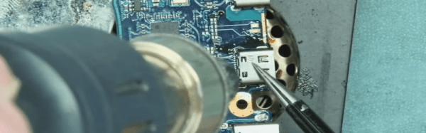
[Marcio Teixeira] needed to recap an old Apple Macintosh motherboard, and came across a simple hack to use common paper staples as a temporary heat shield (video, embedded below) during hot air rework. The problem with hot air rework is minimizing collateral damage; you’re wielding air at a temperature hot enough to melt solder, and it can be take quite a lot of experience to figure out how best to protect the more delicate parts from being damaged. Larger items take longer to heat due to their thermal mass but smaller parts can be very quickly damaged from excess heat, whilst trying to remove a nearby target.

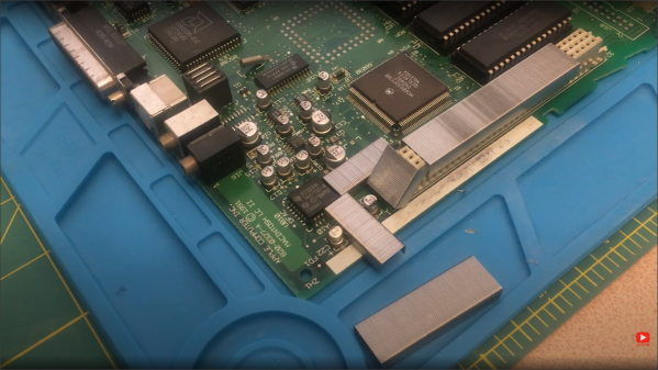
The sharp edges of plastic connectors are particularly prone, and good protection is paramount. Sticky tapes made from polyimide (Kapton), PET, as well as metallic options (aluminium tape is useful) are often used to temporarily mask off areas in danger of getting such collateral overheat. But they can cause other problems. Kapton tape, whilst great at withstanding the heat, tends to distort and buckle up a little when under the blast of the rework pencil. Not to mention that some brands of tape leave a nasty sticky transfer residue all over the board when exposed to heat, which needs additional cleanup.

Maybe a box or two of staples might be worth adding to one’s bag of tricks, after all more options is always good. If you’re less interesting in hacking with a hot air work station and much more in hacking a hot air rework station, here you go, and whilst we’re on reworking duff computers, here’s what happens when a Hackaday writer tries his hand at fixing his son’s Xbox.

Continue reading “Quick Hacks: Using Staples When Recapping Motherboards”