For a DIY reflow setup, most people seem to rely on the trusty thrift store toaster oven as a platform to hack. But there’s something to be said for heating the PCB directly rather than heating the surrounding air, and for that one can cruise the yard sales looking for a hot plate to convert. But an electric wok as a reflow hotplate? Sure, why not?
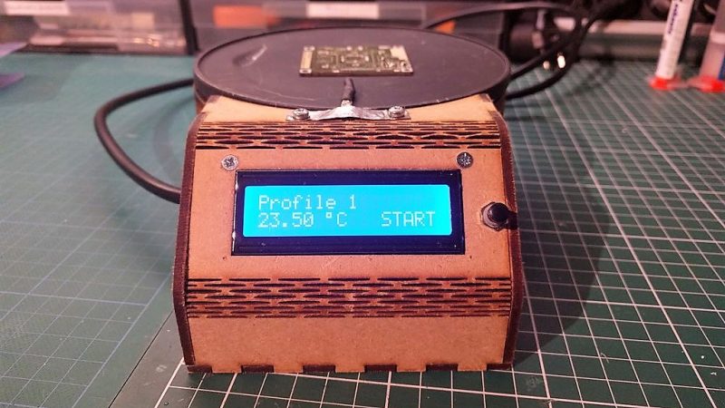
At the end of the day [ThomasVDD]’s reflow wok is the same as any other reflow build. It has a heat source that can be controlled easily, temperature sensors, and a microcontroller that can run the proportional-integral-derivative (PID) control algorithm needed for precise temperature control. That the heating element he used came from an electric wok was just a happy accident. A laser-cut MDF case complete with kerf-bent joints holds the heating element, the solid-state relay, and the Arduino Nano that runs the show. A MAX6675 thermocouple amp senses the temperature and allows the Nano to cycle the temperature through different profiles for different solders. It’s compact, simple, and [ThomasVDD] now has a spare wok to use on the stove top. What’s not to like?
Reflow doesn’t just mean oven or hotplate, of course. Why not give reflow headlights, a reflow blowtorch, or even a reflow work light a try?


I wonder if putting a special clear patch of ground plane somewhere to clip a temperature probe to would help more accurately track the temperature of the board itself in the toaster-oven scenario where you are not directly heating the board but merely heating the airspace around it? (although newer toaster oven with quartz or ceramic elements rather than nichrome wire transfer most of their heat by radiation rather than conduction or convection so maybe it wouldn’t make much difference).
Just arrange one of those hand held remote IR temp sensors at suitable
distance for divergence to cover the whole board (as often put on the
label on the side of the handheld unit). Put it on an angle so there
is no convection affecting the sensor on the hand-held unit and feed
the display to the controller
ie
The remote IR sensor with the red laser pointer or use the chip itself
I was thinking “A flat wok???”
But I see now that it is the heating surface that a wok is placed upon.
Using wood to hold a heater seems like a potential problem.
It is indeed a concern, but I made the case such that the hotplate doesn’t touch the wood. Only the feet of the hotplate, which are much cooler are used to bolt the two together. This is also explained in my instructable, for people who want to replicate it.
It seems problematic heating the bottom of an FR4 board to get solder to melt on the top. Maybe it works for hobby stuff, but that can’t be good for getting predictable temperatures. The temperature distribution probably depends on the copper in the board, and the components that are on top.
I think it would be better if you put a little doghouse over the top, to create an oven around the board.
Here comes the “wok the dog” joke!
Exactly my thought, I was gonna ask if there was a lid left from the wok pan of the original heater setup.
The heat from the heater then doesn’t fly past the board it stays around it, heating the components on top more efficiently. Just like normal cooking…
I’m sure the whole setup appears to work like a charm, but I really wonder what stress this puts onto the PCB.
It’s pretty common to do, even in small-scale production. Conductive heat transfer is much faster and more uniform than convective or radiative transfer like you get in an oven, so getting good results is actually quite a bit easier than using an oven. It also doesn’t matter that much where you probe the temperature since there is pretty decent thermal contact they reach equilibrium quickly.
To get the best results though you need a lab plate or one especially for reflow because they have a lot more thermal mass in the plate and distribute the heat very evenly. They are also much flatter so you have good thermal contact. Hotplates for cooking aren’t as even and can be a bit trickier, but still work well.
Works extremely well and has actually advantages over an oven for sensitive parts because the pads are obviously receiving most of the heat not the casing (which may be plastic) or anything within. Of course there’re also disadvantages, the largest one being that only single sided reflow is possible.
Very nice build. I am withholding a very funny, at least I think so, Wok joke.
Why not give reflow in steam a try too? :D
Get yourself a high pan, some Perfluorpolyether (aka Galden®) and cook your print up in no time and without running any risk of overheating your components. The only issue you might get is either with moisture absorbing components (“exploding” components thanks to the water turning to steam very fast) or maybe some other thermal stress problems if you just drop the cold board into 230°C hot steam.
You beat me to it! I was just starting a build very similar to this. I bought a flat heating element from eBay and was going to build the hotplate from scratch. You have already done all the software for me now!
The main difference is I am adding a fan that can be controlled for cooling to help keep the temp accurate and the hot plate will be much smaller.
Great work, and this will help my project a lot.
I tried it on breadboard before to assemble but, during testing, I realized button doesn’t work: with actual code cicle don’t start, whenever button (connected to arduino D13) is connected to GND or not, as indicated in your schematic. So I tried to connect with a pull up resistor to positive and it starts! It is a mistake in schematic or I missed something (I tested without any heater connected)