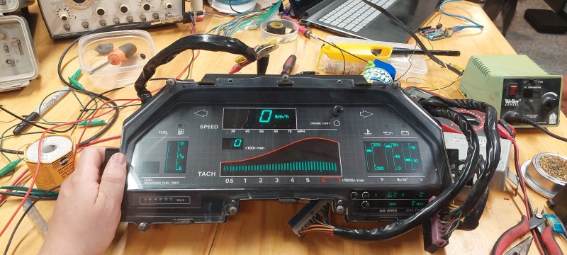
You don’t have to be a car enthusiast to recognize that the 1984 Nissan 300x dash is a work of art. The graceful swoops and multisegment VFDs evoke an aesthetic that reminds us of a particular era. Rather than replace his dash with something drab and modern, [Evan] modified his dash to accept input from newer devices. Many of the sensors that feed directly into the dash are becoming harder to find as the years wear on, and rather than spoof every old device, [Evan] looked at each gauge.
Temperature and oil pressure are variable resistance sensors, and by removing half the voltage divider, it becomes a variable voltage sensor, as modern temperature sensors can output a voltage from 0 to 5. The tachometer required tracing the signal through the PCB as it expects a pulse every time a cylinder fires. By simulating cylinder pulses with a function generator, [Evan] found the filtering circuit and the microcontroller pin monitoring it. An optoisolator to protect the delicate MCU makes it easy to pipe the signal directly in.
Of course, not everything needed to be modified. A vacuum sensor provides a signal to the dash to indicate how much power the engine produces, which is pretty easy to spoof with a teensy connected to the CAN bus. All these mods are easily reversible and allow [Evan] to keep rocking the iconic dash with a more modern engine.
It’s an incredible hack that offers a view into how to trace, understand, and hack old electronics. Of course, if you’re keeping old built-in car bits, why not keep the carphone but connect it to your smartphone?


That is one awesome looking dash, and an amazing example of two hobbies complimenting each other perfectly!
All this has been figured out and documented on the forums for years now what hasn’t been is how to get a different fuel tank sensor to work with the fuel tank gauge i wish that would have been done here.
Is that not just another one of those big power resistors making up half of a voltage divider for the fuel sender to be the other half? I didn’t do that because the car that this is going into has a rebuilt factory sender working fine, but this board seems to have the same topology for measuring analog voltages for all the sensors. Grab a connector pinout, and check continuity to the inside pin of one of those resistors, once you know which one it is, remove the resistor and voila, you have a 0-5v analog input. If you want to replace it with a different float, then measure that resistance and calculate the new resistor. I can even do the math if you tell me what the original fixed resistor and the range of both the old and new sensors was.
The fuel units are well understood.
https://github.com/Z-Karma/Z31-fuel-level-sender-characterization
https://github.com/Acmex2564/Z31-FLCU
Z-katma. What a blast from the past…HH
Should update the voice box from phonograph to digital, or better yet voice assistant…my 84 turbo has an analog dash thank heaven..