There’s a point in a component’s thermal regime that’s between normal operation and overloaded to the point of obvious failure. That’s a dangerous region, because the component isn’t quite hot enough to release the Magic Smoke, but hot enough to singe any finger you poke around with the see if everything’s running right. So if you’re looking to keep your fingerprints unmodified, but you don’t want to invest in a thermal camera, you might want to let this thermochromic breadboard point the way to overloaded components.
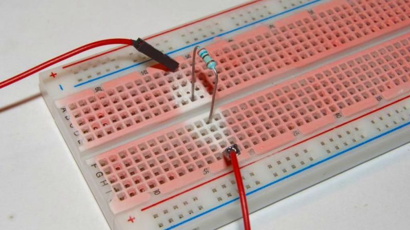
We’re not sure where this tip came from, but judging by the look of the website it was sometime in the late 90s. We’re also not sure who’s behind this little hack, so we’ll just credit [improwis]. The idea is pretty simple — white acrylic paint is mixed with thermochromic pigment, and the mixture is carefully painted onto the plastic surface of a standard-issue solderless breadboard. Care is taken to apply thin coats, lest the paint gets into the contacts and really muck things up. Once the paint is dry you’re ready to build your circuit. We have to admit we’re surprised at how sensitive the paint is; judging by the pictures, the heat coming off a 1/4-watt resistor dissipating 350 mW is plenty, even when the body of the resistor is well above the surface of the breadboard. We’d imagine the paint would point out not only hot components but probably the breadboard contacts too, if things got really toasty.
This seems like such a great application of thermochromism, one that’s a bit more useful than clocks and Pi Day celebrations. If you’re going to try this yourself, you’ll have to track down your own supply of thermochromic pigment, though — the link in the article is long dead. That’s not a problem, though, as Amazon sells scads of the stuff, seemingly aimed mainly at nail salons. The more you know.


This is me.
There are more shenanigans done with that idea.
A good way is to mix several thermochromes with different threshold temperatures, for a wider indication range.
https://www.improwis.com/2017-07-20-ThermochromicBreadboardPrototype/
https://www.improwis.com/2017-07-14-ThermochromicCupsMugPrototypes/
The mix is also handy for visual indication the tea kettle is hot, the tea mug is cold enough to drink, or that a power converter is overheating. A poor man’s thermal vision.
Dear medicine, dear visual prosthetics industry, where are our cyberpunk-class multispectral eyes? It’s 2023, for deities’ rice wine!
A great toy is painting such mix on stickers, and having an easy-to-apply indicators.
The design is the 90’s school, the data are more modern. I just don’t care about the visual appearances and prefer raw content. Though I should make the image galleries CSS-responsive. TODO…
Nice! How comes this never occurred to me, the uses are so many! :)
I love the web design tho, I do miss the clean&simple text/html design of the 90s. :'(
Seems one could soak paper in it, then poke the components through that.
Or just make said stickers. Such thing on a driver heatsink, a chip, or a motor can act as early warning before things go wrong.
For single-use fixed-temperature there are field expedient materials that can log an overheat. My most favorite is a piece of a thermal-printer bill. Cut out a piece, optionally with printed text (or draw something with a soldering iron tip), to have a reference. The material tends to bleach under some conditions and you may want to see that happened instead of seeing a false negative. Above some give or take 70’c, the paper goes dark more or less irreversibly. Attach it with doublesided tape to whatever you are monitoring.
Wow, thermal printer paper – great tip! Thanks!
There are some industrial overheat indicators – simple stickers:
https://www.tme.eu/en/katalog/temperature-indicators_100094/
They are rather expensive though.
It would be nice to find a cheap nonconductive aerosol spray version that can react quickly in both directions.
It could be interesting for use on pcbs.
Perhaps even as a display, adding an addressable matrix of traces to a pcb or even just putting different images on different layers and having it cycle through.
I used this method before thermal imaging was accessible to masses. Had mixed two pigments so that it vas red <30°C, green <48°C and turned creamish white above that. Had it mixed with acetate fishing bags, dissolved in acetone as a binder – it was non conductive and easily washable in ultrasound bath. Just a tiny drop on every suspicious components using thin painters brush and most of the time the faulty component was obvious (who would think that MLCCs tend to fail so often?)
Nowadays, it is useless. Even the chepast $30 thermal imager module beats the crap out of this hack.
A similar method, but using cholesteric liquid crystals, is used industrially. Gives a range of colors, and has spatial resolution good enough even for imaging heat generation on chip dies.
Thinking about cases where an thermal camera won’t work but this will…
When the subject is behind a panel of glass?
Or potted in oil or resin. Or in a (transparent) pressure chamber. All these are common methods to insulate high voltage electronics.
One obvious advantage is that thermochromic does not care about emissivity, so what you see is the real thermal map of the DUT.
I have a shitty Chinese CAT-clone phone with FLIR, just yesterday it helped me diagnose that my incredibly stupid wiring mistake blew up an IO expander. (Didn’t feel the need to test it after the FLIR said the chip was 120 degrees C.)
This hack would also have worked I guess, but as said elsewhere this hack while very cool (heh) is nowhere near competitive now that IR imagers are firmly within reach. Even for a hobbyist the effort of sourcing pigments, mixing paint and applying it can’t be competitive with a thermal imager, especially if you consider the main use of the thermal imager, checking which beers in the fridge are cold and which were just put in.
Thermal imagers have a major advantage.
Their disadvantage, however, is that you have to use one. To know in advance you will need it.
Thermochromes will Be There (until they degrade by ambient UV or other adversities), and provide their low-resolution service.
I’d say, the approaches are best together.
Until we get multispectral eyes.
That isn’t much of a disadvantage. You also have to use thermochromes, you just have to put them on in advance or carry them with you, so they aren’t really any worse than a thermal imager. A thermal imager is easier to carry and use than thermochromes would be. A thermal imager is also a lot more versatile and accurate.
Yes, but… you “install” the sticker only once, possibly during assembly of the machine, and then it is always there, at a glance. Imager is better for overall scene, gives more details, but you have to use it every time you check. I use the stickers for at-a-glance checks for peace of mind. I use imager when I want more data, or when checking the health of the assembly (and finding an underestimated wire just below its insulation melting point…).
What is a better method depends on context.
> Until we get multispectral eyes.
I <3 our mantis-shrimp overlords. Breed me.
whats the name of this clone ?