Snooping in on satellites is getting to be quite popular, enough so that the number of people advancing the state of the art — not to mention the wealth of satellites transmitting signals in the clear — has almost made the hobby too easy. An SDR, a homebrew antenna, and some off-the-shelf software, and you too can see weather satellite images on your screen in real time.
But where’s the challenge? That seems to be the question [dereksgc] asked and answered by tapping into S-band telemetry from an obsolete satellite. Most satellite hunters focus on downlinks in the L-band or even the VHF portion of the spectrum, which are within easy reach of most RTL-SDR dongles. However, the Coriolis satellite, which was launched in 2003, has a downlink firmly in the S-band, which at 2.2-GHz puts it just outside the high end of an RTL-SDR. To work around this, [dereksgc] bought a knock-off HackRF SDR and couple it with a wideband low-noise amplifier (LNA) of his own design. The dish antenna is also homebrewed from a used 1.8-m dish and a custom helical antenna for the right-hand circular polarized downlink signal.
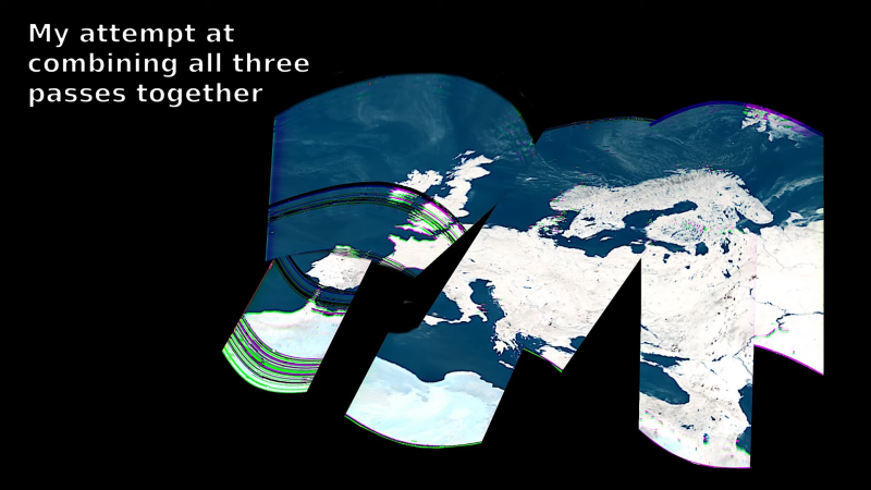
As the video below shows, receiving downlink signals from Coriolis with the rig wasn’t all that difficult. Even with manually steering the dish, [dereksgc] was able to record a couple of decent passes with SDR#. Making sense of the data from WINDSAT, a passive microwave polarimetric radiometer that’s the main instrument that’s still working on the satellite, was another matter. Decoded with SatDump and massaged with Gimp, the microwave images of Europe are at least recognizable, mostly due to Italy’s distinctive shape.
Despite the distortion, seeing the planet’s surface via the microwaves emitted by water vapor is still pretty cool. If more traditional weather satellite images are what you’re looking for, those are pretty cool too.


In QST for April 1971, Paul Wilson described his 2.3GHz converter. Likely used for moonbounce, but a bit later he used it to hear an Apollo mission.
Nobody had SDRs, so they just did things the old way.
Hugin (https://hugin.sourceforge.io/) is a panorama stitcher and might be the tool to let loose on these images! Be sure to use the advanced functions though.
How things have changed.
30+ years ago I modded a scanner with 30Khz filter and built
a decoder from 3 boards ordered from FAR Circuits for VHF APT.
It sent data to the serial port that JVFAX turned into a image.
It was grayscale, no color back then. At that time it was cutting
edge. No idea how much I spent to do all that(a lot) and now can
be done for $10.
I would turn around and send those images via HF Fax to my buddy, in
“almost” real time!! hahaha
Also keep in mind, this was BEFORE I had internet!
Everything was via the US mail….even the software from
Germany. It took 6 months to get it working. Very few folks
could RX direct from a sat back then. :)
Given most RTL-SDRs do not have a RF filter, you can use undersampling to receive signals outside of the supported range. If you add the proper filters for the band you’re looking for, you can still get good performance. For example a baseband ADC operating in the 34th Nyquist zone, with proper RF filters, can still capture a signal decent enough to decode GPS signals, albeit with severely reduced SNR due to the high zone number. So for a signal “just outside the range”, you can probably get it with the 2nd or 3rd Nyquist zone, which still has pretty good characteristics.
I am curious, isn’t it quite hard to build such a band-pass filter? I mean the inductances are super small, like couple centimeters of PCB trace. Are there any techniques you can recommend (besides using VNA and cutting traces ’till they match what you need)?