A Crookes radiometer, despite what many explanations claim, does not work because of radiation pressure. When light strikes the vanes inside the near-vacuum chamber, it heats the vanes, which then impart some extra energy to gas molecules bouncing off of them, causing the vanes to be pushed in the opposite direction. On the other hand, however, it is possible to build a radiometer that spins because of radiation pressure differences, but it’s easier to use acoustic radiation than light.
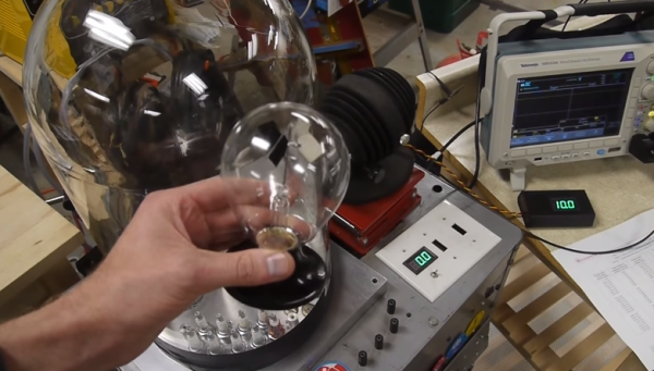
[Ben Krasnow] built two sets of vanes out of laser-cut aluminium with sound-absorbing foam attached to one side, and mounted the vanes around a jewel bearing taken from an analog voltmeter. He positioned the rotor above four speakers in an acoustically well-sealed chamber, then played 130-decibel white noise on the speakers. The aluminium side of the vanes, which reflected more sound, experienced more pressure than the foam side, causing them to spin. [Ben] tested both sets of vanes, which had the foam mounted on opposite sides, and they spun in opposite directions, which suggests that the pressure difference really was causing them to spin, and not some acoustic streaming effect.
The process of creating such loud sounds burned out a number of speakers, so to prevent this, [Ben] monitored the temperature of a speaker coil at varying amounts of power. He realized that the resistance of the coil increased as it heated up, so by measuring its resistance, he could calculate the coil’s temperature and keep it from getting too hot. [Ben] also tested the radiometer’s performance when the chamber contained other gasses, including hydrogen, helium, carbon dioxide, and sulfur hexafluoride, but none worked as well as air did. It’s a bit counterintuitive that none of these widely-varying gasses worked better than air did, but it makes sense when one considers that speakers are designed to efficiently transfer energy to air.
It’s far from an efficient way to convert electrical power into motion, but we’ve also seen several engines powered by acoustic resonance. If you’d like to hear more about the original Crookes radiometers, [Ben]’s also explained those before.