Dipole antennas are easy, right? Just follow the formula, cut two pieces of wire, attach your feedline, and you’re on the air. But then again, maybe not. You’re always advised to cut the legs a little long so you can trim to the right length, but why? Shouldn’t the math just be right? And what difference does wire choice make on the antenna’s characteristics? The simple dipole isn’t really that simple at all.
If you’ve got antenna questions, check out [FesZ]’s new video on resonant dipoles, which is a deep dive into some of the mysteries of the humble dipole. In true [FesZ] fashion, he starts with simulations of various dipole configurations ranging from the ideal case — a lossless conductor in free space with as close to zero diameter conductors as the MMANA antenna simulator can support — and gradually build up to more practical designs.
We’ve got to admit that we were surprised by how much the wire diameter affects the resonant frequency of these theoretical antennas — the chunkier the wire, the lower the resonant frequency, which is defined as the frequency at which the antenna’s impedance has only a resistive component. On the other hand, material selection plays a role, too, with copper wire being the best choice in terms of loss, followed by aluminum wire and then iron pipe, which is very lossy at small diameters. Luckily, these differences even out with increasing conductor diameter.
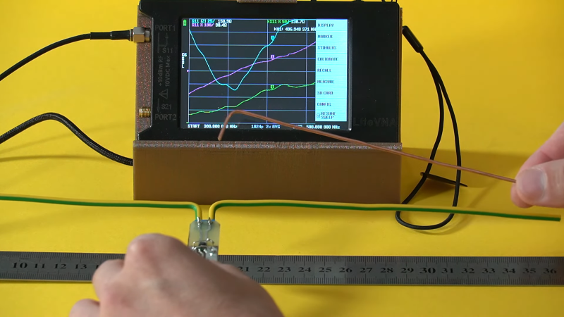
The most interesting part of the video for us was the experiments with practical antennas, which he builds from different materials and tests on a LiteVNA — kind of like a NanoVNA on steroids. As expected, wire thickness plays a part in antenna bandwidth — the finer the wire, the narrower the bandwidth — and the measured resonant frequency worked out to be pretty much what it was in simulation. Insulation on the wire had an unexpectedly huge effect too, pushing the resonant frequency down around 25 MHz.
Thanks to [FesZ] for this effective demonstration of designing antennas for the real world.


Long story short: the math assumes things like the speed of light in vacuum, but adding air and other media in between changes the speed of light slightly, so the math goes off.
In labs where we had access to top of the line network analyzers, when lab time was running short… our error bars were always attributed to multipath propogation. Our Professor agreed (!?)
What a lab report hack!
Because no realizable system exists in isolation, besides possibly the universe, everything is slightly off when considered as an ideal system for very-near approximation purposes.
Is it meaningful to say that the universe exists in isolation, when there’s nothing outside of it? (Technically, not even “nothing”).
Tautologically, yes, there can only be one everything. The challenge is figuring out whether what you call everything actually is.
Yes, but how many everythings there are is not the same question as whether it is “isolated”. From what would it be?
Humans on Earth have a saying: “Cut it long and trim ’til it works.”
It’s also important to keep the symmetric/unsymmetric relationship in mind.
The dipole is usually symmetric, but the coaxial cable is not (it’s unsymmetric).
So you can’t just attach an dipole to an RG58U or RG213.
Welly, you technically can, but this results in sheet waves and RF in the shack.
The coaxial cable will also radiate, which is unwanted.
That’s what many CBers in my place didn’t understand, btw.
They simply made a dipole and wired it to coaxial cable, then blaming the 1/2 lambda dipole for being a troublemaker.
They now use a DV27 long, Gainmaster or similar antenna instead.
To fix that dipole problem, an 1:1 Balun can be used. It can even be bought in assembled form nowadays.
Or, someone can use a “stub” made of coaxial cable. It will directly be attached to the dipole and handle high power.
Another workaround is to use ferrites to block sheet waves. They come in various forms and are always recommend.
Especially on power cords of appliances and accessories.
Last but not least, there’s another problem.
Reflections in cheap coaxial waves, even if new. They can be seen in combination with a VNA and a dummy load/terminator connected on the cable that’s being tested.
Another factor is the lenght of the coaxial cable itself.
At one point, an unlucky lenght can cause high SWR (1/4 lambda or a multiple, I vaguely remember).
In old days, hams made sure the lenght of the coaxial cable matched the operating frequency/the band of choice accordingly.
Coaxial cable lenght weren’t random, by any means.
PS: Another tip: A tuner/matchbox doesn’t belong in the shack, but directly to the feed point of the antenna. Otherwise, the coaxial cable will be “tuned” and may start to radiate, as well.
An except is, maybe, if the coaxial cable is 1/4l. In that case the cable impedance is equally to the antenna feed point.
The radiation problem still persists, though. Lots of ferrites or a “coil” (ring) made of coaxial cable is required.
PS: RG58U is outdated, please consider using RG213 or any other high quality vable.
It’s not about losses and power, but QRM. The shielding of RG58 is too poor nowadays.
QRM in your home or garden will sneak through the RG58 inside the receiver.
I’m talking from experience, btw.
Anyway, these are just suggestions, as a start. Please double check what I wrote. Vy73s.
To clarify a bit for non-HAMs (such as me ;).
QRM is man made interference, so a more specific version of RFI (radio frequency interference).
QRM is not a classical three letter abbreviation. It is part of a standardized collection of three-letter codes, called Q-code. While QR has no official meaning, it can be taken as a prefix meaning “(q)uery in (r)adio communication”.
See also https://en.wikipedia.org/wiki/Q_code
The initial list seems to be mostly alphabetical with no clear correlation between meaning and the last letter, which could be because it was meant to be a language neutral code.
See https://en.wikipedia.org/wiki/Q_code#Early_development
QRM and QRN however do have a convenient correlation with their meaning: “(m)an-made interference” and “(n)atural interference”.
Suggestion: when sharing knowledge, it helps to introduce special terms with a brief explanation, as otherwise it’s just experts “teaching” experts. Or reduce specialty terminology and simply say, man made RFI.
It would take a long time to teach Q-Codes, I am still learning. QRM and QRN are used all the time though, and are the first ones I learned. Another non Q-Code is ‘Alpha Hotel’ which is the cause of some QRM ;)
If you know what QRM and QRN mean it’s obvious, but if not and it appears without more context in a phrase (“QRM in your home” could mean anything), it’s quite confusing. Had to search the web for longer until I knew it’s a Q-Code.
What about chicken ladder balanced line?
Um, it’s great if the shack is in a hen house? :)
Or why not 300Ω twin lead?
What on earth is a ‘sheet wave’?
“sheet waves”
?????????
Standing wave?????
Undesired common mode : https://en.wikipedia.org/wiki/Common-mode_signal
Excellent! Thank you very much! ^^ vy73s
My bad. The online dictionaries say “sheath waves” and “jacket waves”..
In the commenting block above I was referring to what we casually call “Mantelwellen” and I didn’t want to make the mistake to do a litetal translate to “mantle waves”. So I tried to remember that alternative term. 🙂
For someone like me, English is a really really weird language sometimes. It has sayings and terms that are so strange. I never occured me that something like “(undesired) common mode” could have any relationship with the matter, for example. I’m not saying it’s wrong. It’s just the weird English terminology, that catches me off guard (do you say so?). In my native language, there are short and precise casual terms for certain technical things.
Wikipedia says “Sheath current” is the English term for “Mantelwelle”. A web search seems to confirm the meaning of this term.
German can be a clear language, but I don’t think that “Mantelwellen” is a good example (sheath current has the same problem). It suggests that the waves are in the “Ummantelung” so the outer isolation/plug, not the “Schirm”/mesh of a coax cable. Außenleiterwelle would be more clear.
https://en.wikipedia.org/wiki/Braid-breaker
Braid breaker is also quite clear, since a coax cable has only one braid. Less ambiguous than sheath or Mantel which could make you think a dielectric is somehow involved.
Brain breaker is an awful term. It’s not breaking the braid in any way, and doesn’t even operate on (just) the braid. It even works when there IS no braid.
A common-mode choke is inserting a high impedance for electrical signals than are common (in phase) to the two conductors, whether it’s coax or twinlead.
So call it a common-mode choke. That’s exactly what it is and does.
(Cant reply to Paul, so reply goes here): Some actually *do* break the braid and use capacitors to bridge the break in the braid (and the center conductor):
https://en.wikipedia.org/wiki/Braid-breaker
Also, no it’s *not* the same as a choke, see the link.
Actually breaking the braid (and the centre conductor) and inserting a capacitor is called a “DC block”, describing exactly what it does. Which will work on ladder line or twinlead too, not just coax cable.
The term describes the circuit (and it’s circumstances) correctly, it’s not merely a DC block, that can be a simple capacitor.
A braid breaker is more, see the schematic (and the scenario of use):
https://upload.wikimedia.org/wikipedia/en/9/94/TVIdiagram.png
Furthermore it’s not like the shielding and the one inner conductor will pick up the exact same noise, like for twisted pair cabling or in differential signaling, so it does make sense to focus on the braid in the naming.
‘Sheet waves’?
Standing waves, possibly, or radiative losses due to mismatch of feedline and antenna, causing RF signal to be fed back to the transmitter, which can be negated by use of an isolator(or circulator if you prefer), which is a directional coupler that uses magnetics to ‘isolate’ the transmitted forward signal, and the reflected mismatch fed back to the transmitter, is routed to a 50Ω load and not directly towards the transmitter.
RG-58 is junk, plain and simple.
For best performance, use Heliax, which is a corrugated solid copper shield around a copper plated aluminum center conductor.
Common size is 1/2″, and has low loss by design per 100′.
Any angles in a dipole antenna must be accounted for in measurements, as must element diameter.
You also change the radiation pattern of a dipole when you introduce angles into the design, instead of actual 90° from the feedpoint.
Obtain a VNA and learn it’s use, they are cheap, but highly recommended, far better than a simple SWR bridge.
You might also look into an actual SWR bridge to use with a service monitor.
They have 3 ports, and are highly accurate to test a complete system, or individual antenna components such as feedlines and antennas separately. I have an Eagle SWR bridge I use with my service monitor, a model RLB150X3, ports are: Source, Reflected, and Combined.
The source and reflected ports connect to your equipment, and the combined port connects to you DUT (Device Under Test).
I hope this helps with your design planning..
What I’ve always appreciated about antennas is that, while you can do the math to run simulations to compare various modifications, it all makes sense. In other words, once you develop an understanding for how they work, you can estimate what a given change will have on performance. And, there won’t be surprises!
Personally, I find the effect of the immediate environment on the antenna very difficult to “calculate”.
Radioelectricity is really a black art…
I can see several issues with this analysis:
1. The NanaoVNA calibation is sone with 50 ohms, but the antenna is 73 ohms. Why not calibrate for 73 ohms?
2. Do this stuff in an anechoic chamber, not holding it up with a wet salty bag near a parallel steel ruler.
3. Who cares about the resonant frequency or “bandwidth”? The interesting part is radiation efficiency, I learned this years ago. Tune your antenna by maximising RSSI while listening to a distant source. You might find the best result isn’t predicted exactly by return loss/VSWR. The TX performance is a mirror of the RX performance in this respect (for the same frequency).
and I wish there was an edit button!
There’s been wishin’ like that around here for a loooong time. Please keep it up, maybe your wish will come true – someday…
This!
I’m an old ham and former broadcast engineer (AM radio mostly). We almost always designed the antenna (usually the tower) for best radiation, and then designed transmitter, final, transmission lines, and other equipment to efficiently feed this antenna. (Usually with a matching network at the base of the tower fed by ladder line to the shack. The towers were closer to “end-fed” antenna’s than dipoles, and used a LOT of radials and other tricks. ) SWR was never a goal.
During Covid, I designed and built an adjustable dipole to test various theories that I had been taught over the years. (A ham antenna must operate over a lot of different frequencies. so a single channel AM radio station’s example can only go so far.) HAM’s really need an adjustable solution.
https://github.com/AD0MZ/All-Band-Adjustable-Dipole
A similar design…
https://tune-a-tenna.com
This article by AE4YW was very helpful in understanding that a good ham might want to use practices the broadcast guys have used for years.
http://www.hamuniverse.com/ae4ywresonance.html
No matter what the band, I was able to confirm that adjusting the radiator length close to the theoretical optimum length worked best.
At first I had forgotten about a dipole’s impedance of 70 ohms when I noticed that resonant point was not the lowest SWR. This is why you have to think of transmitting equipment as a “system”.
BTW…
I knew a guy who guilt a dipole of soldered together aluminum cans to get extra bandwidth. Too bad we couldn’t afford a VNA back in the 70’s.
The math does work when you use the right math and factor in the correct variables, like others have mentioned cat connect coax directly to a dipole without accounting for coax. also the space between leads, feedlines etc. – So in my opinion this post seam more like trollolling post my someone without RF experience, and if they do, omg, super troll post
i always see and hear to divide the frequency by 468 to get a half wave dipole, but in the real world that always came up a little short and had much better luck dividing 492 by the frequency for half-wave dipoles in the HF part of the spectum
Hmm. Something funny with that math. Got your numerator and denominator mixed up?
And what kind of units are they in?
yeah i backasswarded the first example, divide the frequency by the formula is how its done
Still out by a factor of Pi or so. 7 Mhz is 40 m band, so half wave would be 20 m long, not the 66 or 70 your formula says. Is that in feet?
i am sticking with 492 it seems to work for me no matter what part of the HF spectrum i build an antenna for, and when it comes to trimming a dipole its easier to cut a little off than it is to put it back on
The insulation certainly has an effect, and that’s because the wire has both inductance as well as capacitive effects to itself … which is also why thickness matters. I once modeled in EZNEC+ a 3.5 MHz vertical as a wire enclosed in a PVC tube with pure water (which is an insulator with a dielectric constant of roughly 3 if I remember correctly) inside the PVC tube. By pumping water to various levels from the base of the PVC tube I could (according to the model) tune the antenna over quite a large frequency range.
So you could tune in that pirate station with the good dance tunes by pumping up the volume?
No … so I could transmit with a matched load. I’ll leave the funky dance tunes to you.
Pump up the volume…of water in the tube, I think he meant. Ahh puns!
Even with the incorrectly-sized dipole, you’ll still be “on the air”; just not as efficiently or with the best ERP you could possibly have(and associated reception). And even if it is “correctly” sized, that size only works “perfectly” for a very narrow frequency range(and its harmonics). You’ll be “off” to some degree within any given band. Only if you are tuned to the nadir of the wave will you start getting SWR damage, and then only at higher power, depending on the quality and design of your radio.
There’s a lot of wiggle-room with RF.
That’s not really true. Many of the current low power (and low cost) rigs that have become very popular lately will blow the output stage with an SWR as low as 2:1 depending upon the phase.
That’s why they invented tuners.
Reflected power is reflected power. It means what it says. A high return loss or low vswr is an indicator that that the power is going to either coupling to the ether or dissipated in the transmission line. Now an antenna can be inefficient, have power absorbed by nearby obstructions, coupled into other antennas or things that act as antennas, reflected by other stuff to point in a different direction than desired, etc. In fact one or more of these things happens in nearly all “in the real world” installations.
I managed a rooftop (horizontal array) with over 100 vertical antennas and you could measure about 1/2 to 1 watt being received (coupled by the array) from each antenna. Times 100 antennas. Do the math….
There’s a lot more to it than matching return loss with a network analyzer.