For those living before the invention of the transistor, the modern world must appear almost magical. Computers are everywhere now and are much more reliable, but there are other less obvious changes as well. Someone from that time would have needed a huge clunky machine like a motor-generator set to convert DC voltages, but we can do it with ease using a few integrated circuits. This one can take a huge range of input voltages to output a constant 5V.
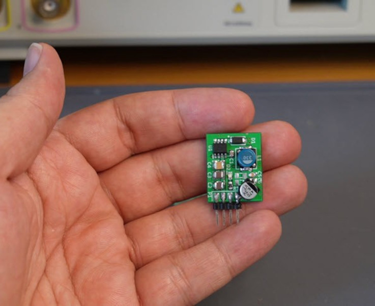
The buck converter was designed by [hesam.moshiri] using a MP9486 chip. While it is possible to use a multipurpose microcontroller like something from Atmel to perform the switching operation needed for DC-DC converters, using a purpose-built chip saves a lot of headache. The circuit was modified a little bit to support the higher input voltage ranges and improve its stability and reliability. The board is assembled in an incredibly tiny package with inputs and outputs readily accessible, so it would be fairly simple to add one into a project rather than designing it from scratch.
Even though buck converters, and other DC converters like boost and the mysterious buck-boost converter, seem like magic even to us, there is some interesting electrical theory going on if you’re willing to dive into the inner workings of high-frequency switching. Take a look at this explanation we featured a while back to see more about how buck converters, the more easily understood among them, work.


I read this as converts 8v into 100v, AKA a boost converter.
I see now the title should have been: “accepts up to 100v”.
I feel the title could be less ambiguous.
Could definitely be useful for a 72v-82v Golf cart or small EV
I read it exactly the same way.
same!
Off Topic but :
I recognize your name from “Find My” project on GitHub :) Thanks for your work !!
>Could definitely be useful for a 72v-82v Golf cart or small EV
Certainly not the device pictured. There’s no way you’d want to run anything more than a couple amps for short periods of time through a connector that small.
The device pictured is meant to provide 5v, presumably to lower voltage electronics, not to drive the high amperage electric motors.
same !
It is LN2556 buck converter voltage range 8V to 100V 5A
Me too, spamtastic headline
SEPIC converters are more interesting though not as efficient. They have much more use with renewables as the supply can vary above and below the output.
They’re low efficiency and at higher currents, finding a coupling capacitor is difficult. A flyback is probably better at every power level that a SEPIC converter can operate at. Cuk and Zeta converters are also interesting to read about, but you never see them in products.
Is there enough isolation clearance for 100V? The Vin and Gnd traces seem awfully close together. It seems like only a tiny bit of carbon tracking will short out Vin.
No but don’t let that bother you as it didn’t bother the “creator”. You are not going to run it from the wall unless you are in a specific part of Japan so you are going to be dropping voltage though tradional means anyway …. then you have to rectum-fry it
and there seems to be no printed schematic
Could it why not? it would probably shit its brains out before being of practical use as the part is a Chineseium junk part ran out of spec
The part is from MPS, far from chinesium!
And spec is 95 V with 100 V as absolute max…
Just gotta love the latent racism, typed completely unironically on a Chinese made laptop, tablet or phone.
Just awesome.
“The part is from MPS, far from chinesium!”
Yea….sure… ALL parts from china are “Genuine” …right?
It’s sold on Aliexpress. With prices starting around 0,3USD to ~2USD for one IC.
Also running an IC at its absolute max values is just plain stupid. Especially if the part might be fake.
MPS is somehow California and China based. But they alos offer automotive ICs. Although my experiences with manufacturers like TI or Onsemi are on average better than with MPS
My rule of thumb is 0,5mm/100V. This includes quite a bit of safety margin. In theory it can be as small as 0,2mm for naked traces on the PCB.
KiCad has a table for electrical spacing in it’s calculator tools based on IPC2221. and for lead/termination (A6 column) they quote a distance of 0.5mm for up to 100V.
Other columns have much smaller distances, but those are mostly for inner layers and for products with conformal coating.
It’s also not just for the isolation, but also for creepage, dirty PCB’s, and bugs creeping over the PCB.
0.5mm trace spacing for 100v seems way un-conservative—playing with fire even. If there is a pinhole in the solder mask resin then you have an air gap. And for that, my rule of thumb has always be one inch per kilovolt. Look at some tear downs of good phone chargers. Some even mill a gap in the PCB between the “mains” side and the low voltage side. Frequent contributor, Ken Shirriff has a great expose on cheap chargers: http://www.righto.com/2012/03/inside-cheap-phone-charger-and-why-you.html
I want to scream every time a client mentions IPC2221. In any case, you are reading table 6.1 incorrectly. Look again. No, look again.
For protection against shock, IPC2221 is not relevant. Reference IEC62368-1 for creepage and clearance where Basic, DI or RI is required for protection from shock hazards.
I had this discussion before, on Elektroda.pl forums. There was a big one when a respected maker presented his headphone amplifier in metal case, and few trolls attacked him for “not enough spacing”. When asked of concrete rules and recommendations they couldn’t even indicate a relevant norm, as there are few different documents, some proper for Poland, some proper for EU, and some covering USA, and neither quite match. Not mentioning that access to many of them is behind a paywall, and no sane amateur will pay for them.
My rule of thumb is based on IPC2221B, for traces with no coating. It’s more than enough for devices used at home. For any other cases I’d suggest adding conformal coating – I used dedicated polyurethane spray.
As for headphones amp the spacings were much more than 0,5mm, and the spacing between any pin and (powder-painted) case was 3mm, with plastic insulation sheet taken from broken ATX PSU (one of the trolls wanted to know, what was the specified norm for that sheet).
There are concrete rules for this. IPC2221B is not a safety standard, it is a manufacturing standard. If you search online, you can usually find a copy of the safety standard that is relevant to the product.
Perhaps from 100V to another 100V trace, but certainly not from 100V to something ELV, like 5V. Unless you want everything to be considered live.
As someone who was born after the transistor, but before CPUs on a single die, the state of technology today is awesome! I’m so happy to have PCs, the internet, smartphones, and dozens of other modern pieces of technology. Some people seem to be unable to accept any technology more advanced than what they had in high school, I don’t get that. I suppose I got that from my father who was born in 1932, and who first worked with computers in the ’50s. He never let technology get ahead of him and was eager for new technology until he died in his ’80s.
“Some people seem to be unable to accept any technology more advanced than what they had in high school, I don’t get that.”
It’s simple, really. Technology of the late 20th wasn’t a black box yet, it was still understandable.
Same goes for classic 74 series ICs, they had certain functions. Logical components, always being interchangeable.
AND gatters, OR gatters etc. Same goes for processors. An Z80 was usable as both a central processor of a CP/M system, as well as a microcontroller (say, a as a heart of a floppy controller board).
Us people from the 70s-90s knew were i/o ports in memory were located, we knew how to program an AdLib music card or mode 13h of the VGA. We had control over the harware we found so fascinating at tbe time.
Now it’s the reverse. It’s nolonger “our” hardware, so we nolonger have strong feelings for it. Simple as that. I hope I could make you understand. Bye.
We still have ‘some’ that with our SBCs and micro controllers. You can still read/write registers of the GPIO for example, but not to the extend of what we ‘used to have to do’.
One the thing the ‘black box’ has done, is allowed us to think at a ‘higher’ level of functionality. Ie. We can write our code at a higher level and not be distracted with the actual low level workings, which in theory, should allow us to build more complex things easier and in a timely manner. For simple example, I don’t write the ‘PWM’ code for running a servo. I use a library already written to tell it to go 50% and it does. Don’t get me wrong, I enjoyed (and still do to some extent) the challenge of writing base level code to registers and optimizing the routines to run in minimum memory, or faster, and such back in 80s and 90s, but also enjoy all the tools, processors, we have today and not be bothered with mode 13, drawing an anti-aliasing line/circle in assembly, or whatever! Only way to progress is to build on the foundation that is already laid, so to speak, rather than keep rebuilding the foundation.
“I’m so happy to have PCs, the internet, smartphones, and dozens of other modern pieces of technology.”
Most of this was already available in the early 80s. CP/M PCs since the 70s, arcade cabs, Packet Radio, international news agencies via RTTY on shortwave, CompuServe in US/Canada/etc, Videotex in Europe (BTX, Minitel), Nifty in Japan etc. Fidonet mailbox network..
We had international e-mail in the 80s, already. It was one of the earliest technologies to overcome boarders. E-mail existed before the interne was made accessible to the public in the 90s. By then, tens of thousand individuals (or more) already had an email address at CompuServe, Nifty or a national telecommunications service.
Here in former W-Germany, we had public BTX terminals before reunion. They were to be found in train stations, air ports, postal offices, in public areas of bigger cities (say,in front of a museum).
http://www.oeffentlichetelefone.de/oeffentliches_btx_terminal.html
Moral of the storry: History wasn’t as gray as some people make it sound.
The digital age had already begun when the microelectronic was invented.
We didn’t need the internet, we were already online before! We had digital video conferencing in Germany, via ISDN. It was independent of the internet.
But these early implementation was far away from what we have to day like comparing a Mofa with a modern car or even a jetplane.
Hard to see how this is a “hack”… it’s just the normal application schematic from the datasheet of a DC/DC converter. There are 1000’s more.
While not a hack on its own, it might be a valuable component to inspire us to hack something else. I’ll allow it.
“Component of the Week” would make a great running column.
100VDC is of course, quite a bit of DC voltage, but also not quite to rectified mains (not even to US split phase 120Vrms, which is about 165V peak), so you’re looking at either PV (single modules don’t run nearly this high), or large battery packs to get up near this voltage.
For those looking for a driver IC that can handle rectified mains (or just higher voltage DC), TI’s UCC28881 is a nice part to take a look at. 700 Vin(max), but only good for a couple hundred mA (with which you can do quite a bit, but it isn’t 1A). However, it isn’t isolated, so there are considerations to be made in device design to maintain safety, esp if working from a mains source.
Im would expect this converter to bes desigend for higher voltage battery systems, like 48V or 72V. Probably alos for “mild hybride” automotive applications.
I need convert small power to 5V
from 0.1V to 24V to 5V USB
solar, panel , every battery 1.5, 3.7 AAA , 18650 etc, car battery 12 or 24
to power my computer
ST, TI and Linear have specialized parts to step up from very low voltage and low power sources. Low power like a TEG cell at 200mV. 0.1V is too low I think.
Why does your computer require so many different power options?
One thing I really liked about the obsolete 34063 was it’s built in current limit, and unfortunately this is a very rare feature. I also find this very strange. Those SO-8 SMPS IC’s nearly always can deliver between 1 and 3A, and you have to size the inductor, so it won’t saturate at those high currents. Quite often you just need something between 20mA and a few hundred mA just to run a microcontroller and some surrounding circuitry. They even manage to cram a 2A buck converter in a SOT23-6 these days, but again, an adjustable current limit is very rare.
I really like the high input voltage capability. Ti also has something similar, (Some up to 80V, but also 100V) but those are also relatively expensive. Projects like motor controllers where the whole controller is piggybacking on the motor, and a uC power supply is derived from the motor supply voltage is a good example for wanting a high input voltage for an SMPS.
I’ve also been looking at the STSPIN IC’s. A single micrcontroller, with built in (quite high voltage) SMPS, MOSfet drivers and analog opamps for current sensing. Price is reasonable, but without second sources a design around that chip is difficult and uncertain to maintain. (And there are a few BLDC motor controllers around STSPIN on the projects section here.
In the MC34063A, It’s used to limit the peak current through the transistors and inductor and short cycles one switching on period when the current limit threshold is exceeded.
Most switching regulators now use specialized regulation schemes to allow for vary large vin-vout differences and operate at high speed and low / no load while still maintaining regulation and minimizing ripple voltage in the output.
LN2556 is new chinese Led driver Buck converter from 8V to 80V with 5Acurrent