While for some of us it’s a distant memory, every serious electronics hobbyist must at some point make the leap from working with through-hole components to Surface Mount Devices (SMD). At first glance, the diminutive components can be quite intimidating — how can you possibly work with parts that are literally smaller than a grain of rice? But of course, like anything else, with practice comes proficiency.
It’s at this silicon precipice that [Larry Bank] recently found himself. While better known on these pages for his software exploits, he recently decided to add SMD electronics to his repertoire by designing and assembling a pocket-sized CO2 monitor. While the monitor itself is a neat gadget that would be worthy of these pages on its own, what’s really compelling about this write-up is how it documents the journey from SMD skeptic to convert in a very personal way.
At first, [Larry] admits to being put off by projects using SMD parts, assuming (not unreasonably) that it would require a significant investment in time and money. But eventually he realized that he could start small and work his way up; for less than $100 USD he was able to pick up both a hot air rework station and a hotplate, which is more than enough to get started with a wide range of SMD components. He experimented with using solder stencils, but even there, ultimately found them to be an unnecessary expense for many projects.
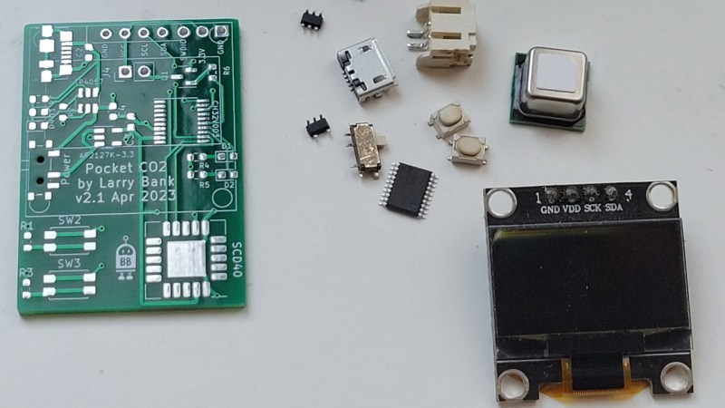
While the bulk of the page details the process of assembling the board, [Larry] does provide some technical details on the device itself. It’s powered by the incredibly cheap CH32V003 microcontroller — they cost him less than twenty cents each for fifty of the things — paired with the ubiquitous 128×64 SSD1306 OLED, TP4057 charge controller, and a SCD40 CO2 sensor.
Whether you want to build your own portable CO2 sensor (which judging from the video below, is quite nice), or you’re just looking for some tips on how to leave those through-hole parts in the past, [Larry] has you covered. We’re particularly eager to see more of his work with the CH32V003, which is quickly becoming a must-have in the modern hardware hacker’s arsenal.


I found myself thrown into the deep end of SMD 25 years ago supporting laptop design. Once over the thought that it’s difficult, and armed with the correct tools, it seems much easier. For quick designs, I can etch a single sided board at home and have it ready and loaded with parts in an evening, no drilling needed. Routing is easy too if you don’t mind a 0-ohm jumper here and there. Parts are much easier to get these days in SMD form also. Avoid leadless chips and super tiny discretes and don’t look back…
Completely agree, but the real eye opener for me was a good flux pen and non magnetic tweezers! It makes all the difference! Using a good no clean flux i can easily hand solder 0402 components with a chisel tipped iron with lead free solder. After i discovered flux i even stopped using throughhole components for protoboards. 0604 and sot23 components are perfect pitch for soldeing on hole pads.
Just ordered a bunch of ch32v003 to test the fantastic work done by cnlohr:
https://github.com/cnlohr/ch32v003fun
It can now be reflashed with an arduino.
In SOP16 format it is way easier to solder.
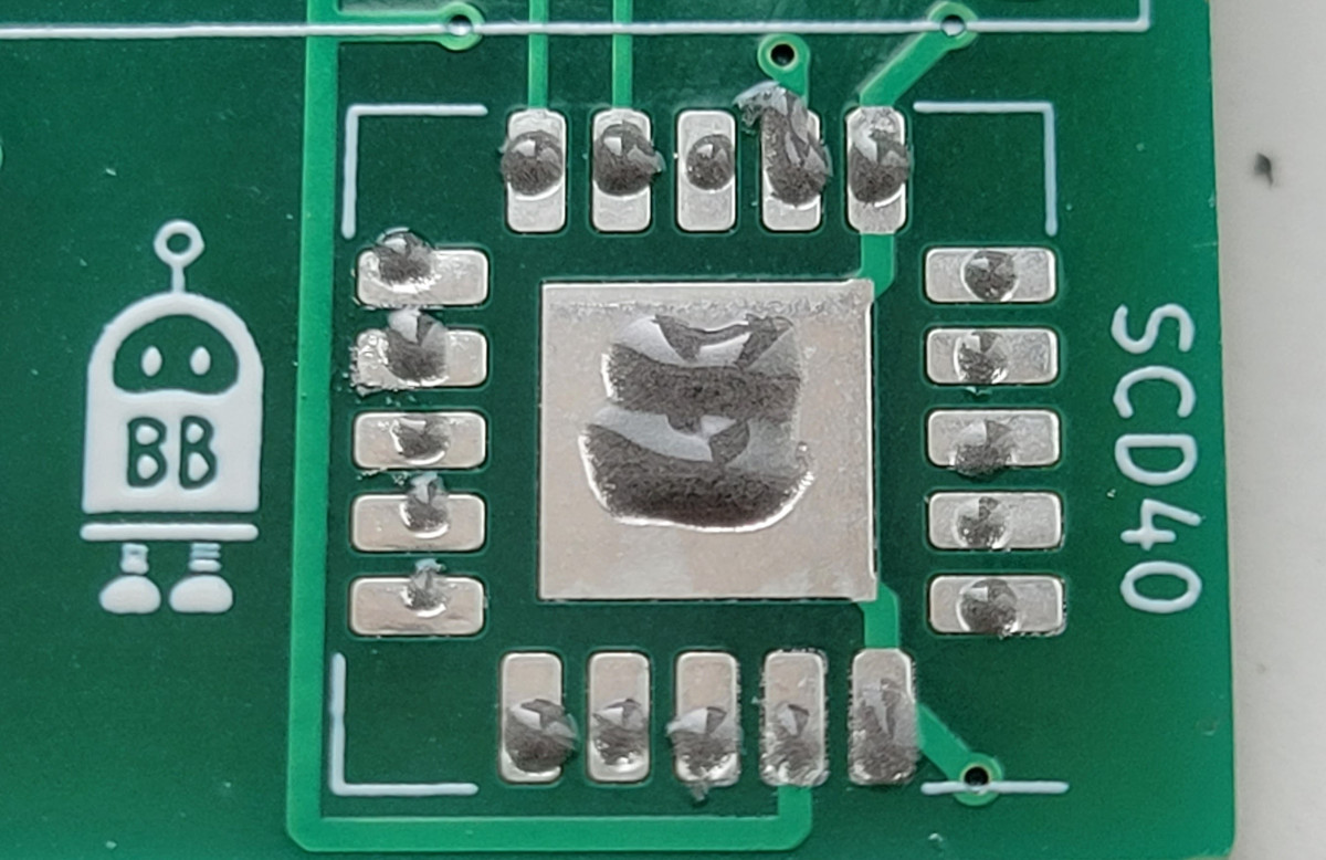
I noticed on the photo little mounds of solder on the pads which will affect the placement of the part. It may leave the part raised and not flush. Heating with hot air will require heating all of the pads in attempting to place the part and solder evenly. Risk of overheating the part and/or circuit traces.
Soldering SM components can be interesting when the leads are close together. I use the following technique on all SM components. I have found that there is usually enough solder on the pads from fabrication for this to work. Place some flux on the pads. Then set the part in place. Apply the soldering tip to a couple of leads on opposite side of the part. It is now tacked in place sufficiently to finish soldering the part with solder and I will not move. If there is not enough solder from the circuit board production, apply a small amount of solder to one pad on opposite sides of the part. Then solder as previously described. I have used this technique on parts with 20+ leads on each of 4 sides. BTW a table mounted light with a magnifying lens is really helpful on closely spaced leads. When finished soldering the board, I flush it with alcohol and DI water to remove any residual flux.