If you need to send data from sensors, there are plenty of options, including a bewildering selection of wireless methods. Trouble is, most of those protocols require a substantial stack of technology to make them work, and things aren’t much easier with wired sensors either. It doesn’t have to be that complicated, though, as this simple two-wire power-and-data interface demonstrates.
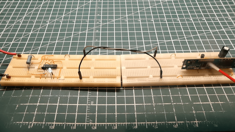
As with all things electronic, there are tradeoffs, which [0033mer] addresses in some detail in the video below. The basic setup for his use case is a PIC-based sensor — temperature, for this demo — that would be mounted in some remote location. The microcontroller needs to be powered, of course, and also needs to send a signal back to a central point to indicate whether the monitored location is within temperature specs. Both needs are accommodated by a single pair of wires and a tiny bit of additional circuitry. On one end of the twisted pair is a power supply and decoder circuit, which sends 9 volts up the line to power the PIC sensor. The decoder is based on a CD4538 dual monostable multivibrator, set up for an “on” time of one second. A trigger input is connected to the power side of the twisted pair going to the sensor, where a transistor connected to one of the PIC’s GPIO pins is set up to short the twisted pair together every half-second. Power to the PIC is maintained by a big electrolytic and a diode, to prevent back-feeding the controller. The steady 0.5-Hz stream of pulses from the sensor keeps resetting the timer on the control side. Once that stream stops, either through code or by an open or short condition on the twisted pair, the controller triggers an output to go high.
It’s a pretty clever system with very simple and flexible circuitry. [0033mer] says he’s used this over twisted-pair wires a couple of hundred feet long, which is pretty impressive. It’s limited to one bit of bandwidth, of course, but that might just be enough for the job. If it’s not, you might want to check out our primer on current-loop sensors, which are better suited for analog sensors but still share some of the fault-detection features.


Great article! :-)
A hundred feet toe-to-toe or heel-to-toe?
…”one bit of bandwidth”… should be “one bit per second of bandwidth”, just to be pedantic
Isn’t that baud?
Looks as ‘baud’ as poking the noise…
Apart from the jokes, let’s reconsider the article. It discusses a 0.5Hz signal, which implies a raw bandwidth – or should I say ‘badwidth’ – of 0.5bps. However, considering it encodes three distinct symbols (temperature threshold, short circuit, open circuit), we can actually achieve a bandwidth of 1.5bps over a baud rate of 0.5. So, it’s not just about the baud rate, but also how efficiently each signal change can carry data
It doesn’t “encode” those, it’s just a watchdog circuit. If the light went on, you always have to check whether it’s a temperature alarm or the wire got broken.
Pretty sure my garage door safety light beam works on a similar principle, sending power over a (not twisted) pair to both ends of the sensor chain, then occasionally listening for a short to indicate no obstruction. (Genie opener, not the other dominant manufacturer)
This can even be bidirectional at considerable bit rates for twisted pair like cat5 or coaxial.
Looks like they’ve just re-invented 1-wire with parasitic power.
There’s 1-wire sensors and GPIO devices for all sorts of purposes, and the bus itself can reach up to 1000 ft.
He saved one wire. Isn’t it amazing?
Just a joke, btw.
Can 1-wire use the earth for a return path? Then it would finally actually be one wire.
Probably, but it wouldn’t go very far because the current loop would be too sensitive to noise. You have to use a twisted pair to get the full distance.
You might want to consider the ESD performance if you are going 100 feet. I used to run smart sensors over 4 wire telephone cable, power on one pair, RS485 on the other pair over that sort of distance. I got to replace ESD rated 485 transceivers every couple of years at the previous place I lived, and a couple of times a year at the current location. Went with a radio link and small solar panels 5 years back, no more lightning problems for sensors.
Sounds like kind of a TDMA approach, multiplexing power and data with self sync’ing. Pretty clever. It seems to me that the power portion of the cycle with sufficient filtering could power the remote long enough for the data portion of the cycle to send more complex data than just one bit per second, though.
Or maybe I just misunderstood the concept.
ya, works fine with one foot of wire. Slap 100′ and you will have a whole different outcome.
Did you even bother reading the article to the end?
Rather than shorting the power to ground, it could use a pull-up resistor at the microcontroller and a switched pull-down resistor at the sensor end. Then you read the data using an ADC-capable pin on the PIC. The data starts with a couple of start bits spaced _x_ microseconds apart, and ones and zeros depend on the state of the line every _y_ microseconds until a full data payload is sent. I had to write a protocol controller for a PIC that did bidirectional data flow on a single wire based on such a time-dependent algorithm. The controller sent a command, at certain points in the data frame it switched to receive mode for the remote device to respond, and both devices calculated a CRC to ensure data integrity.
Rather than an MCU on the sensor end, you can make/buy a dumb 4-20mA temperature sensor
and read it via near-end MCU ADC across a 250R resistor. 1V to 5V drop represents a low to high temp reading, respectively, vs. just a trip point.
Only in case you didnt know it, there is an industrial bus called HART that uses 1200Baud
transmition on top of standard 4-20mA wires.
There are existing circuits for this. DS8500 or NCN5192.
That would make your live much easier for bidirectional transmission over two wires on
top of power.
Olaf
I made a data-over-power standard for work at one point. The master provided 5V or 8V power. It would toggle to transmit data between the two levels at 2400 baud. And used a 5V Zener to step it down to 0-3V for the UART receiver.
I transmitted back using current. The sensor normally draws 5mA, so I would draw an extra 9mA with a transistor and resistor connected to the UART transmitter. The receiver for it was a small resistor and opamp to output the right voltage levels. Easy-peasy with minimal components.
With an op-amp at each end you can make it bidirectional. 4 current levels and the receiver at one end compensating for it’s own transmission side.
Another scheme is to have the power side signal with polarity reversion. I rectified power filter at the other end and two currents as return transmission.
On the power side have a current sense resistor before the polarity switching bridge.
For higher rates move up closer to RF and uses separate bands that don’t have harmonics.
I pulled a similar trick on a design a few years back. 2 pics. One with power and the sensor, signalling serially to the other, which had a simple display and a couple of push buttons. Ok it’s the other way around in this article, but, you know, its similar. 2 wires; gnd and data. The trick was to use Manchester encoding, which is always wobbling 0,1, even when “line idle”. Signalling through a transistor. A cap and a diode at the remote to generate the volts for the pic and the minimal display. An exercise in bit-banging. I got 9.6kbps out of it over about 20 metres, signalling at only 5V but I’m sure I could have pushed that faster. Gotta love Manchester encoding with its built-in error detection, and to be able to generate volts out of it was a big bonus.
I didn’t know it even had a name. I have always called it PSK – crudely so from the days of computer cassette interfaces.
But to my point, that there is no inherent error correction. If you recover the clock which is easy as there is only CLK and CLK/2 then you can detect errors but unless you are using a more complex protocol like parity in a RS-232 like way then you can’t really correct an error as far as I can see. Even then you need a frame parity or CRC as what if the original error is in a parity bit?
The correct data are 2 of 4 quads 10 and 01. An error is the other 2 of four quads 00 or 11. But for example if you receive 00 than how can you tell if it should have been 10 or 01 without some form of parity or data redundancy?
As for speed you can get over a MHz (500kb/s via now redundant Nyquist theorem) on a single twisted pair in current mode, like RS-485. And after that there’s cheap TV coax than can still be used in current mode but a shielded twisted pair works just as well and is cheaper but you have reduced distance as Eddie currents in the shielding increase parasitic load so coax will run much further.
We used to run 9600 voice channels over Coax. Hangon , 18 x 3^5 = 4374 (not 9600) @ 3.4kHz bandwidth per voice channel so about 15 MHz on shielded twisted pair where the varying rates and direction of the twists were made to cancel parasitic reactence. But we needed repeaters that were powered over the same wires every 15km.
Not sure though about the math. On one of these many channels we sent a 1.2kHz sine and 2.2 sine and used the lower side band of these to recover both clock referenc (1kHz) for the suppressed carrier and phase so technically the use of side-bands meant that the signal was from -7.5MHz to -2.5MHz LSB and 2.5MHZ to 7.5MHz USB with a base band in the middle that was progressively the same right down to a 3.4kHz baseband.
RE: Manchester Encoding error detection:
Basically, each bit has a 0-1 (a “0” in my case) or a 1-0 (a “1”) transition in it. If you get a 0-0 or a 1-1, then that’s a violation and you can reject it, like you said above. It’s detection, not correction. Manchester encoding has the advantage that it’s self-clocking, though of course the bitrate is essentially halved.
Looking back at my project files I see that I used a 250uS inter-frame gap of all 1’s, which gave my basic inter-PIC coms something to key on to get ready for the start bit and it also allowed the cap on the other end to get a nice charge, though with fresh eyes on the project and code, I don’t think I really needed that gap. I was using the signalling violation to make my coding a bit simpler, at the expense of data throughput, of course.
Digressing, I agree with you and other posts about 485. More recent 485 IC’s (e.g.: Maxim MAX487 and MAX1487) offer “quarter-unit-load” and slew-rate limits, allowing for up to 128 nodes on the same bus. These chips exhibit lower amplitude high-frequency harmonics, which help to reduce EMI and reflections (especially those caused by badly terminated cabling). I reckon you’d get over a kilometer out of them through a suitable TP cable, though they are only rated for 250kbps. Regarding 485, its not just the 120ohm termination resistor that’s important, you also have to properly bias the two legs (pull-up on one and pull-down on another) so that when no node is in tx mode (i.e.: they are all in rx mode) and the line is high-impedance, the line is dragged to a “1” (i.e.: “idle”) by the bias resistors. Learned that the hard way, doh!
Being an ol’ fellow this encoding has two meanings to me.
The first is digital- You have D (Data), EN(Data enable), Q1(Clock quadrant 1- 0 degrees), Q2(Clock quadrant 2 – 90 degrees), O(output)
Modulation – D is ANDed with EN (which is Q2) and then the result is XORed with Q1
O = (D AND Q2) XOR Q1
Then there is the analogue where D is gated in the same way but – the carrier frequency which is twice the data rate is equally mixed with the data and the upper sideband is added with the carrier to generate the modulated output. (Old speak).
The difference to common analogue modulation schemes is how close together the data rate and carrier are (because of it’s poor use of bandwidth).
On a spectrum analyser you would see just two spikes (one F and one 2F) on otherwise flat noise floor so obviously it is easy to discern (filter) one from the other either digitally or via analogue.
So there is no real reason for the clock to be twice the data rate or even for the clock to have a singular frequency.
In real world analogue bearers (wire, optical) it is the higher frequency harmonics that cause the reflections and ringing so it never hurts to shift the lower end of the bandwidth down a little.
So you make the “0” state of the carrier signal half the length of the “1” state and immediately achieve a 50% increase in data rate and have three spikes on the spectrum – the third being lower than the original two. Clock, Clock + data and Clock – data or in analogue terms carrier frequency, lower side band, upper side band (once called double side band) so you can use the same demodulation (decoding) techniques to recover data.
Then if you wanted you can mix these two principles using the first as the data conveyor and the second as a redundant bit, for bit level error correction – why not if you have the bandwidth of a dedicated signal bearer. In Analogue we called this NRZ or Non-Return to Zero where in digital terms “Zero” represents the error condition.
So in the first principal you have there shortening of the “0” state
10 => “11” “0”
01 => “0” “11”
Or yo could have a shortening of the clock (carrier)
10 => “11” “0”
01 => “00” “1”
Either way you now have a redundant bit, for bit level error correction.
And as for the ol’ RS-485, current loop protocol. Well all PC mainboards now have matched length loop signals for high speed. Most FPGA’s allow the digital equivalent – Differential Signalling. We used to just call these “balanced”-referenced to ground and “unbalanced”-referenced to the other half of the “pair”.
What was old is new again lol. It’s exactly the same but now we have far better chips that hide the analogue aspects from us so that we don’t have to understand them.
Most of the old communications signals like RS-485 and even signals on a floppy disk “bus” or early SCSI were “open collector outputs” where each device could output a “0” but not a “1” and this is what we had “active low” signals. Today we would call that a wired AND where a bunch of signals are connected together and any one of them can pull low but none of them can pull high – that was done with a shared “pull-up” resistor.
When I wanted to learn about CANBUS I built a system based on Arduino Uno clones with CANBUS interfaces connected using four core phone cable. Each node had a dual phone socket allowing the nodes to be daisy chained. I ran the CANBUS over one pair and 12v over the other.
What I found was that the CANBUS worked perfectly at 500Kb in spite of the cable being flat, not twisted, but the real problem was volts drop on the power over long runs. I am curious as to what cable is being used for long runs?
To compensate for voltage drop, use a higher voltage, for example 24Vdc, and then give each node it’s own SMPS circuit. First, the higher voltage needs less current for the same power over the cable, and because each node has a local regulator, the voltage drop over the cable does not matter much.
This is also explicitly built into RS485 and CAN. Both are specified to have their signalling levels defined to -7V (or there abouts). So even if the GND voltage of a remote node is raised a few volts because of the current though the GND conductor, it still all works within specifications.
Thanks for your reply. Unfortunately 12v is the max for Arduinos and some nodes will be closer to the source than others.
I was just making the point that for long cable runs, volts drop can be more of an issue than signal integrity.
The 12 Volt limit is a thermal limit assuming 1 Amps through the board regulator – the actual regulator can take up to 20 Volts for a typical Arduino board. You would use a separate regulator and surge protection circuits to drop down to 5 or 3.3 Volts for the board anyways, since the line would introduce additional noise that might trip the MCU otherwise.
An Arduino by itself is not hardened against power supply interference. For example, if you want it to run off of 12 Volt power in a car, you can expect anything from 11 – 14.7 Volts with transient peaks up to 50 Volts. Any “real world” application of these things requires power conditioning.