[Trent M. Wyatt]’s CPUVolt library provides a fast way to measure voltage using no external components, and no I/O pin. It only applies to certain microcontrollers, but he provides example Arduino code showing how handy this can be for battery-powered projects.
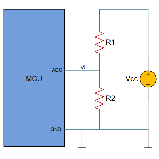
The classical way to measure a system’s voltage is to connect one of your MCU’s ADC pins to a voltage divider made from a couple resistors. A simple calculation yields a reading of the system’s voltage, but this approach has two disadvantages: one is that it constantly consumes power, and the other is that it ties up a pin that you might want to use for something else.
There are ways to mitigate these issues, but it would be best to avoid them entirely. Microchip application note 2447 describes a method of doing exactly that, and that’s precisely what [Trent]’s Arduino library implements.
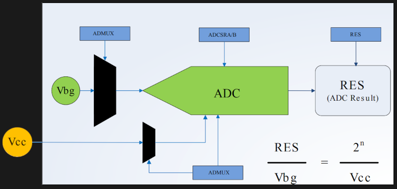
What happens in this method is one selects Vbg (a fixed internal voltage reference that is temperature-independent) as Vin, and selects Vcc as the ADC’s voltage reference. This is essentially backwards from how the ADC is normally used, but it requires no external hookup and is only a bit of calculation away from determining Vcc in millivolts. There is some non-linearity in the results, but for the purposes of measuring battery power in a system or deciding when to send a “low battery” signal, it’s an attractive solution.
Being an Arduino library, CPUVolt makes this idea very easy to use, but the concept and method is actually something we have seen before. If you’re interested in the low-level details, then check out our earlier coverage which goes into some detail on exactly what is going on, using an ATtiny84.


Ähmm, guess how precise measurements have been done for the last decades on any micro that does not feature a Vref pin… Yes, exactly that way!
Nothing new for a “pro”, but maybe good information for the young players….
Well, “precise” being relative with just one real ADC channel, since measuring the VCC and measuring the other voltage happen at different times. Using an external Vref means that the ADC is sampling both the reference and the signal at the same time.
Whether that is relevant depends on the circuit in question, because the signals you’re measuring may or may not be referenced to VCC, e.g. with ratiometric sensors, in which case you don’t want to use a fixed reference.
This is obviously only going to work if your microcontroller is powered directly off the battery with no regulator in between, right? ie. usually only relevant to 5V tolerant microcontrollers so a lithium ion battery’s entire range is in spec. Or you run directly off something like two or three AA batteries which is becoming increasingly rare.
Very good point.
Well, it’s relevant to check your assumption that your 5 Volts IS actually 5 Volts.
If you have ratiometric signals, then everything is a fraction of whatever voltage you get, but if some of the signals you’re getting have an absolute reference at the source, then your regulator tolerance and loading matters. You can’t just assume that 5 Volts is 5 Volts.
And even with ratiometric sensors, point in case:
You have a sensor with a full range response from 10-90% of Vin. The sensor consumes 1.5 milliamps from source. It has 30 feet of cabling to your Arduino. What is the voltage drop across that cable?
Practically unknowable. You have to pull an extra wire from the sensor’s input voltage to your Arduino’s AREF pin, so you know what the actual voltage at the end of the cable is, so you can estimate the 10-90% range. You could do that in code after some calibration, but then if you have a different cable, and/or a different length of cable, your fudge factor no longer works.
Exactly. Plus voltage is not an accurate proxy for battery charge.
Although that is absolutly true, it is a “good enought” indicator for checking if the battery is “full”, “medium charged” or “almost dead”.
Sure. But is there a different thing you can measure that gives a better picture? You can keep track of how the battery performs. But you still measure the voltage don’t you?
The better method is to coulomb/charge count to estimate state of charge of the battery. Generally the reason why voltage is a poor indicator of remaining charge is the discharge curve of lithium based batteries tends to be pretty flat right up until the battery is nearly dead so you are trying to extrapolate remaining percentage from only a ~half volt drop from fully charged to dead. Any noise or measurement error only makes the estimation even less accurate. I wouldn’t say it’s entirely useless though, as for the purposes of low battery warning or cutoff it’s still better than nothing.
It’s not really flat. It’s just that it depends on the load, the ambient temperature, and the age and wear of the battery, and it’s non-linear.
Example:
https://www.tme.eu/Document/d53147e0a451a710ac15dcb449ea3da0/ACCU-18650-3.5.pdf
This cell goes pretty linearly from 4.0 Volts to 3.3 Volts for almost the entire charge, except it’s +-10% depending on the load at normal temperature. What that means, at maximum load the full cell looks like it’s already a third depleted. This gets worse when the temperature goes down. Somewhere around -15 C any load will make the cell look like empty.
It’s quite common for 3.3 V-rated devices running on a 3 V lithium primary cell.
Good point. The moment I hit send I thought of this ;)
This is a great technique, and one that a lot of people forget about — worth bringing up more often than once every decade! :) And certainly nice to have it in a simple code library.
BTW: I love that in the linked article (from 2014) there are people saying “this is nothing new”…
Drop a comment here if this was new to you.
I read about it in your book, so this is not new to me :-P
I’m still wondering what is the use of the trick. Most µC these days use a DC/DC to convert from whatever source voltage to the 3.3V or 1.8V they need. If you measure Vcc you’re measuring the DC/DC converter output which is supposed to be regulated.
Is it precise enough to detect defect in the DC/DC output that could be linked to the actual source voltage? (Except for the obvious brownout effect?)
In most case, I don’t think so. In the end, you’ll still need a pin that’s somehow connected to the source voltage (or on a net that’s linearly related to it).
Exactly what I’m using it for!
Safety checks in the system, product tests after manufacturing etc!
You’re absolutely right that if there’s an external buck/boost controller regulating Vcc, this trick won’t work (or if the microcontroller has an internal buck/boost but no way to directly measure Vcc without mapping a pin)
However, most of the atmel microcontrollers covered by the article are specced to work happily from 2.7-5.5v, meaning they can run just fine through the entire usable range of most common battery chemistries without an external voltage regulator.
Allowing Vcc to drop during use does put some limits on what you can do with the microcontroller, but if minimizing device size, pin count, complexity, cost, and/or power consumption are concerns – and those not *that* common uncommon as design goals – this is a handy trick to have in your toolkit.
also, even if Vcc is fed through a buck converter you can often still use this trick to identify a low battery state. Say you have a standard lithium-ion cell regulated down to 3.3v. Once the battery starts dropping below 3.3v, it will no longer be regulated and this trick will start working again. Unless the battery is very tiny that still gives the end-user plenty of time to change or charge it before you reach a battery cutoff or microprocessor brownout scenario. Lithium ion cells will have exhausted most of their useful capacity by the time they drop to 3.3v, so you don’t gain much using a buck/boost converter instead.
I was shocked that this is even possible, much less so simple. (Pun intended)
They say to be nice because we were all newbies once,.but really we are all eternal newbies. Even if you’re an expert in one area, there will always be topics you know nothing about. 99% of the time, we don’t even know what we don’t know. So when your 1% falls in someone else’s 99%, remember that their 1% probbably falls in yours.
Funny. I used this ‘trick’ five years ago when I built a thermocouple-based thermometer in a Pro Micro (clone). Liberal use of sleep modes, but it was always ‘on’ and displaying the current oven temperature. Push a button and it measures the battery voltage using the above-described technique.
It runs off 3 ‘AA” batteries. I just replaced hem for he first time last week. Five years of runtime on a single set of alkalines.
I used this method in a vehicle sensor microcontroller. I needed to know if the power supply was within specification, so I measured the internal regulator instead. If either the external supply or the internal regulator was out of spec, it would come out in the ADC measurement. It’s always a relative measurement, so both can be treated as the input.
is this possible with an esp32 mcu??