We all like to keep our network gear running during a power outage — trouble is, your standard consumer-grade uninterruptible power supply (UPS) tends to be overkill for routers and such. Their outlet strips built quickly get crowded with wall-warts, and why bother converting from DC to AC only to convert back again?
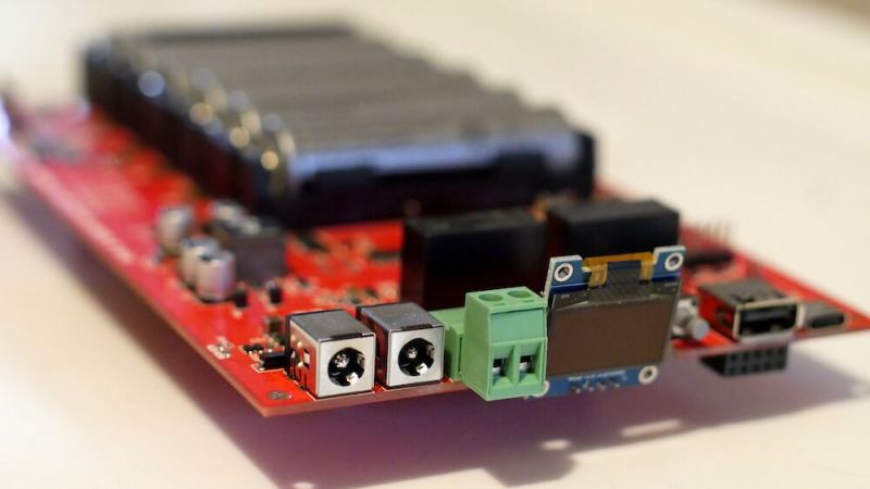
This common conundrum is the inspiration for [Walker]’s DC UPS design, which has some interesting features. First off, the design is open source, which of course invites tinkering and repurposing. The UPS is built for a 12 volt supply and load, but that obviously can be changed to suit your needs. The battery bank is a 4S3P design using 18650 cells, and that could be customized as well. There’s an ideal diode controller that prevents DC from back-feeding into the supply when the lights go out, and a really interesting synchronous buck-boost converter in place of the power management chip you’d normally see in a UPS. The converter chip takes a PWM signal from an RP2040; there’s also an ESP32 onboard for web server and UI duties as well as an STM32 to run the BMS. The video below discusses the design and shows a little of the build.
We’ve seen a spate of DC UPS designs lately, some more elaborate than others. This one has quite a few interesting chips that most of us don’t normally deal with, and it’s nice to see how they’re used in a practical design.


If it needs 3 MCUs to achieve a simple task, it´s almost sure the software side is a clutter mess.
Especially considering that float charging a battery is a single diode and a slight adjustment on the power supply side to compensate.
2 microcontrollers would probably be ideal, 1 would be too few. I can imagine reasons for 3 but it does seem excessive.
Having the web server separate from the BMS seems like a very good thing though, I’d rather have 3 than 1. No idea why they didn’t use an ESP32 and 2 of the same type of small MCU.
Same first thought, though my conclusion was poor design.
but its also 2023 the world is upside down, if you arent choosy MCUs aren’t expensive any more, and are almost always cheaper than specialized chips, some can be had for less than most of the components on the board.
What’s wrong with a little 12v vrla battery and a AC/DC 12v charger? Its a much simpler solution
RV, Marine applications. For the AC aspect, these require you to have/run an inverter. As a full-time RVer, I’ve been working hard to get things OFF the AC system, since most of my electronics are 12v DC anyway. Sure, we’re often plugged into a campground’s 50-amp supply, but when we “boondock”, we are on solar and batteries alone. If I can keep the inverter off, I save that much more power. If we aren’t getting good solar, I can crank up our onboard generator every couple of days for a couple hours to top us off. So power management IS a thing and you can save power in these scenarios.
I came to say I had just bought a DC UPS, after MUCH searching. Not sure I’m 100% thrilled with, but I don’t actually have it inline yet. I bought it to ensure my Synology NAS just stays up during any power flips I might have. I bought the “Junior 5 amp” device here: https://www.powerstream.com/battery-protector.htm
That is what I use and have been using for years, it’s cheap simple and reliable.
So 2 different ARM chips and one ESP … isn’t that a huge SDK-hell?
This device isn’t actually open source, they just make schematics available, and the firmware is open source.
Folks like you who get the results of a ton of someone else’s work and then complain that you didn’t get every single thing are a real treat.
Note that the manufacturer itself doesn’t call it open source either, they are very clear that they publish only schematics, and that only the firmware is open source. That bit just got lost somewhere on the way to hackaday.
Hackaday might have got the idea from the video, it’s literally the first sentence, and the YT thumbnail says “Open source UPS”.
While I do agree that it doesn’t quite meet the fully open source ideals I personally feel this is as open as I could want for from a commercial company selling a product and wish more would do the same. With a pdf schematic and an open sofware repository I have everything I need to repair and maintain. At the same time they don’t give enough away for anyone to just knock out clones at a reduced price without doing any leg work themselves.
Companies should be applauded for going this far and encouraged to do so, not lambasted for not going far enough when they’re already way ahead of the norm for openness.
+1
Criticism, even harsh, is how one find flaws in an idea or design. Everyone is free to ignore said criticism.
When you make something public, expect public discourse.
Folks like you who assume nefarious motive when somebody states facts are the real threat to open discussion. Go back under your bridge, troll.
jaseg did not complain, he provided a very interesting comment that saved me some time. And probably to others as well.
What are you talking about? Because the schematic is only a pdf and not the original CAD file?
The information is all there, the license is MIT. I’m pretty sure you are free to re-enter the schematic in your favorite EDA package, modify it and release your changes in any way that is compatible with the MIT license.
There is a consensus on what open source hardware means, and that does include at least Gerbers so you can actually re-create the board yourself. Note that the manufacturer itself doesn’t call this open source, and is clear that only the schematics are available for the hardware, and that the firmware is open source. It’s only hackaday’s headline that called it open source, probably because someone in the chain mis-understood something.
The first sentence in the YT video claims the project is open-source.
It seems people don’t understand that ‘open source’ means something and are now getting pissy with because of the ignorance.
This is pretty f****** awesome.
When living on-grid I was using 2 mean well 12v DC converter with ups function.
They got a charging function and believe medical grade.
So, is the software side a clutter mess? Could all of the same functionality been implemented with one MCU and a 555?
And providing a full schematic seems pretty open source to me. Providing physical design details feels closer to straight up creative commons license situation, which is the same thing anyway, right?
For over a decade now I’ve been using the picoUPS which I believe is also open source, but now discontinued from the manufacturer. But it looks like they have other options for lead acid and lithium. Not that there’s a problem with more options, but at least with those ones you can order it ready to go, to save having to order PCBs and all the components yourself.
You might have been able to save some circuitry by using a 20v power tool battery pack (eg Dewalt…)