It’s happened to all of us at one time or another. There’s some component sitting on the bench, say an I2C sensor, a new display, or maybe a flash chip, and you want to poke around with it. So you get out the breadboard, wire it to a microcontroller, write some code, flash it…you get the idea. Frankly, it’s all kind of a hassle. Which is why [Ian Lesnet] created the Bus Pirate: a USB multi-tool designed to get you up and running with a new piece of hardware as quickly as possible.
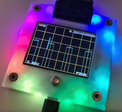
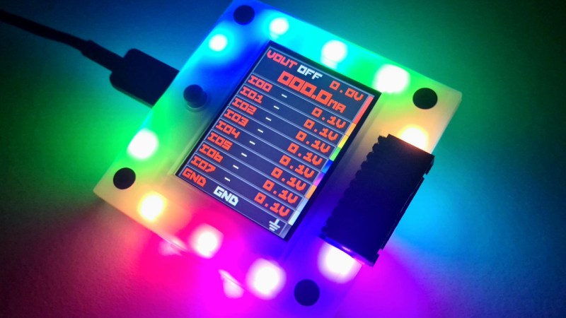
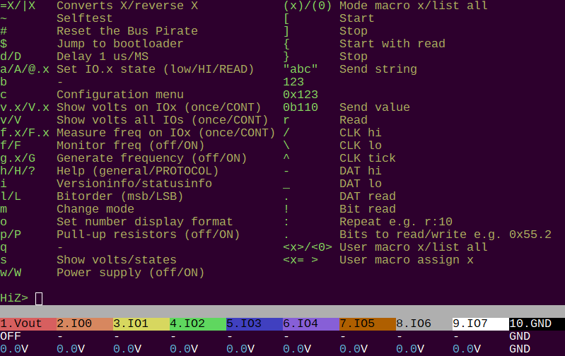
Now, after years of development, the Bus Pirate 5 is available for purchase. Completely redesigned to take advantage of the impressive I/O capabilities of the RP2040, the new Bus Pirate also features a 240 x 320 IPS LCD that can show real-time voltage data and pin assignments. But despite the new display, and the bevy of RGB LEDs lurking under the injection molded enclosure, the primary interface for the device remains the VT100 terminal interface — now with the addition of a color status bar running along the bottom.
 As with the earlier versions of the Bus Pirate, the device includes all sorts of features that should prove useful to the hardware hacker. It can be used as a programmable 1 to 5 volt power supply, complete with current detection and a resettable fuse. With a simple text interface you can send communicate with devices over 1-Wire, I2C, SPI, UART, MIDI, and various RGB LED protocols out of the box, but thanks to its open source firmware, expect it to learn some new tricks before too long. In the announcement post, [Ian] mentions upcoming firmware additions to support JTAG, man-in-the-middle (MITM) attacks, and a very slick oscilloscope that uses the Pirate’s onboard display.
Long time readers may recall that the Bus Pirate started its life right here on Hackaday back in 2008, when [Ian] was writing for us. While we no longer have any official connection to the project, we remain big fans of the open hardware device. There’s a Bus Pirate 5 with our name on it currently working its way through the postal system at the time of this writing, so expect a hands-on look at the new hardware in the near future.


I ordered v4, never used it, by the time I figure out the cryptic config I write a demo in arduino or via any HAL.
No guest checkout? Come on is this 2004 all over again?
Seems so. Shame really.
Be grateful motorsports isn’t your hobby. Everything is from 1997
hahahah Jj you aren’t kidding
check out VCDS for a good time travel laugh https://www.ross-tech.com/vag-com/VCDS.php
aauuugh why would you drop buttons and keep a billion LEDs while also wasting pins with shift registers rather than a proper SPI expander…? I mean, I get cost, but… *a billion LEDs*
This would be sooo useful with buttons and a hacked in battery option.
Agreed. A standalone I2C/SPI test tool would be incredible.
Plus a standalone serial output terminal, or a $40 low-speed scope!
I mean, obviously you can *turn it into* one of those things with a bit of hacking – you suck up some of the I/Os and use a USB-C power source or something. But there’s an SPI bus *right there* and the USB-C charge/power/etc. ICs are so cheap…
Hey there I personally use this one it is capable of 3Mhz SPI and GPIO and I2c over a kernel driver. You can also add it to your device tree to develop your spi/i2c/gpio drivers. And it is super cheap it costs 10 Euro. And you can use all standard Linux mechanisms. I also have a Bus Pirate but I don’t like the commands you have to learn and I personally find it hard to use it for anything other then reading some registers.
https://github.com/frank-zago/ch341-i2c-spi-gpio/pull/22
The ‘scope has already been coded – will come as a software update real soon now
They’re probably still not what you’re hoping for, but I’m rather fond of the I2CDriver and SPIDriver boards (featured on Hackaday a few years ago and still available). Their display provides basic diagnostic info and passive bus monitoring as soon as you turn them on. Alas, they still depend on a USB connection to do anything more sophisticated, but they have a nice cross-platform GUI that at least *feels* like something you’d want on a physical test tool (and also a console interface and python/c++ libraries).
I also have an (older) bus pirate and it’s a more flexible tool overall, but I always reach for the I2CDriver first if I think it’s likely to work.
I generally agree with the sentiment, but the shift registers only require 4 pins from the microcontroller, the same 4 pins you’d use to drive an SPI expander. What am I missing?
Shift registers only give you outputs: an SPI expander gets you programmable ins/outs for the same number of pins. I mean, they could’ve also just creatively thrown an ‘HC165 on there too, sure, but the SPI expander gets you everything in one chip.
I should assume that if they released a cut down version (1 or no LED, maybe 4 channels?) and released it around $10 to get people used to using their software and ecosystem it might go a long way to opening them up to mainstream. People will buy $40-80 Rpi 4 and 5 all day long. But they can start with a $15 Pi Zero.
The vast majority of the cost has got to be just the fact that you’re assembling a PCB, the display, and the enclosure. The parts have gotta be close to nothing: the LEDs are what, a few cents a pop?
I mean overall it’s a great price for what it is, it just really sucks it essentially requires a host.
Does it though? With the button, and a 128MB of flash, it’s a Simple Matter of Programming to turn it into standalone datalogger or flash programmer (like the PicKit3). That’s assuming Ian hasn’t already put that in.
I’m sure the LEDs are WS2812 so only one GPIO is taken hostage, but I agree that a couple more buttons would be welcome.
It did have 3 buttons! But the covid suplychain crisis hit the dac we used so we had to use the rp2040s pwm and that took up the pin for the other buttons.
The look is ugly, I mean *really* ugly, but I wouldn’t care if it wasn’t for all those LEDs which could be so distracting. LEDs are very useful as an output device, but one thing is arranging them in one or more rows and another is scattering high intensity ones in a way they become more distracting than informative. I’m sure it will have success as a cheap sci-fi movie prop.
This VT interface is epic. Can not resist. Ordered.
It looks cool, though I wonder why they didn’t color the channels across the bottom per the resistor color code. They put brown between violet and white instead of to the left of red. The software developer wasn’t a hardware person I guess!
Ugh. Meant to say between violet and GREY. I have to freshen-up on my naughty mnemonic again.
There are 50 shades of grey…
hahah i love how this article is written “But despite the new display, and the bevy of RGB LEDs lurking under the injection molded enclosure, the primary interface for the device remains the VT100 terminal interface — now with the addition of a color status bar running along the bottom.”
for real, that got to the heart of the question. i looked at the beautiful display and said “how could that device be useful? i’d give all of that up for an actual useful interface” and the article doesn’t even get to the third paragraph before setting me straight. good job!
I just dusted off the OG (v2.go) a couple days ago and was sad when I found out that the firmware no longer supports it
That is sad. I still have my v2go in the desk next to me. Gets pulled out when a part needs configuring before installation, or as a AVRDude programmer, or a serial port if the 3.3 or 5V cable one is in use elsewhere, etc. Very handy.
Will have a look at the BP5, really it will be the price and accessories like a test cable set that will make or break the deal for me.
I also dusted off my v3.6 over the weekend to use with Flashrom to revive a corrupt Thunderbolt controller flash on an old Thinkpad.
Aside from the support from older tools like Flashrom, I’m nowadays more inclined to use an FT[24]232H and PyFTDI or MicroPython for my quick and dirty bit twiddling needs.
I don’t really get why they decided to clutter up the ever important usage Documentation with the really weird AI renders that make absolutely no sense and aren’t even related to the product. Was like looking at a train wreck in regards of distracting.
I’d rather have the bare tutorial without any filler.
Cute, but what I REALLY want to know is where can I get a replacement Openbench Logic Sniffer if anything were to happen to the one I have AND RELY ON FOR ALL MY LA NEEDS. Guess I’ll just have to hunt down the specific buffer chip and de/resolder it if anything goes south…
Wow, the original Bus Pirate, Dangerous Prototypes, Ian Lesnet, Sjaak – those are memories from an entirely different planet! I’ll take a look at the new Bus Pirate, but at first glance it seems pricey and the flashy LEDs are a distraction. Do I need a new Bus Pirate? Hmmm… I can get a 24MHz 8 channel Sigrok/PulseView compatible logic analyzer for $10-$12 delivered in one or two days from Amazon – and it just works. So I dunno.
/me says Hi!!
If you need a logic analyzer this is not the one for you, but if you need a swiss army knife (the rp2040 is quite versatile and fast because of the PIO state machines) it could be something. Expecting the price will come later one..
I would prefer a smaller, low-cost model that does not stink (read the article) or blink (that ugly frame around the display).
The display itself is a nice valuable addition
Otherwise: buspirate v5 is available for purchase, nice, but where is the source code gone ?
I personally HATE when some opensource project get traction and community interest but then publish an “updated” version, and no source code. It feels like cheating the open-source community and stealing from it.
You mean this sourcecode: https://github.com/DangerousPrototypes/BusPirate5-firmware ?
I agree on the LEDs, personally preffered a aluminium case without the disco, but Ian did vetoed that :) But in his github (another repro) all the files are there to make your own version without the LEDs. Looking forward to it
You mean this source code: https://github.com/DangerousPrototypes/BusPirate5-firmware ?
I agree on the LEDs and preferred a more solid aluminium case instead without the LED frenxy, but Ian vetoed against it. However in his github all the files are to make your own cost reduced one. Looking forward to it..
From what i read. They actually wanted to use a STM32 combined with a FPGA for obscene amount of power. But then those chips became unobtainable for years during the height of the part shortage. When the RP2040 came out and those showed to be very reliable and affordable to source, it became the new core of the Pirate.