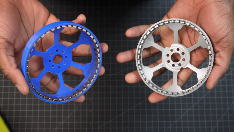
With the popularity of robot dogs, many people have gotten on the bandwagon and tried building DIY versions. Most of them end up attaching a gearbox to an off-the-shelf brushless motor and call it a day. Not everyone goes that way, though, which is why this internal cycloidal drive actuator caught our eye.
Taking design cues from the MIT Mini Cheetah, [Aaed Musa] approached his actuator from the inside out, literally. His 3D printed cycloidal gearbox is designed to fit inside the stator of a BLDC motor. And not just any BLDC motor, but one built mostly from scratch using a hand-wound — and unwound, and wound again — stator along with a rotor that started as a printed part but was eventually machined from steel. Apart from its fixed ring, the cycloidal drive was mostly 3D printed, with everything fitting nicely inside the stator.
The video below shows the design and assembly process as well as testing of the finished drive. It seems to do really well with speed and positional accuracy, and it delivers a substantial amount of torque. Maybe a little too much, though; testing it with a heavy weight on the end of an arm got the stator coils hot enough to warp the printed parts within. But no matter; this was only a prototype after all. [Aaed] says improvements are in the works, including replacing all the plastic parts with metal ones.
Need a little background on cycloidal drives? They’re pretty cool.


How’s vibration?
https://en.wikipedia.org/wiki/Cycloidal_drive
He actually covered that in the video and balanced the shaft with a second disk to offset the imbalance.
It looks pretty smooth in the video and aside form operation being quite loud (likely due to plastic components and no lubrication during assembly, it looks like a pretty well-though-out design.
zowie
that was a pretty comprehensive overview/analysis/description video
I’m still awestruck.
super kudos to Aaed Musa!
The zero backlash bit is a bit disingenuous, because it’s only true if the materials were entirely rigid and there were no gaps.
It’s the idea that because the rollers are always touching, the mechanism would have to “climb a hill” against the curve of the hole, which it cannot. Of course it can because in the bottom position the slope is essentially zero and there is “infinite” mechanical advantage to push against the material.
It’s the same as in the case of the tight rope, where an infinitesimal force is able to push the rope away from a straight line, because the centering force in the straight configuration is zero and only begins to grow as you push it. There is a centering force, but it won’t reach center unless there is zero external forces on the structure, which is just as good as having backlash.
In other words, the rollers would have to push infinitely hard against the wobble plate for there to be “zero backlash” in the mechanism. If there is even an micron of a gap between the roller and the wobble plate, there will be a surprisingly large amount of backlash, since the roller has to roll for quite a bit before the materials actually start to compress together and provide that returning force.
HaD commenters really are the most cantankerous bunch, huh?
Yeah, you gotta use metal in the internal parts. Motors get hot for a reason. 3D printed parts use thermal plastic, and when it gets hot, melts.