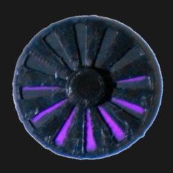
A common way to visualize that a 3D printer’s extruder motor — which feeds the filament into the hot end — is moving is to attach a small indicator to the exposed end of the motor’s shaft. As the shaft turns, so does the attached indicator.
Small movements of the motor are therefore turned into larger movements of something else. So far, so simple. But what about visualizing very small extrusions, such as those tiny ones made during ironing?
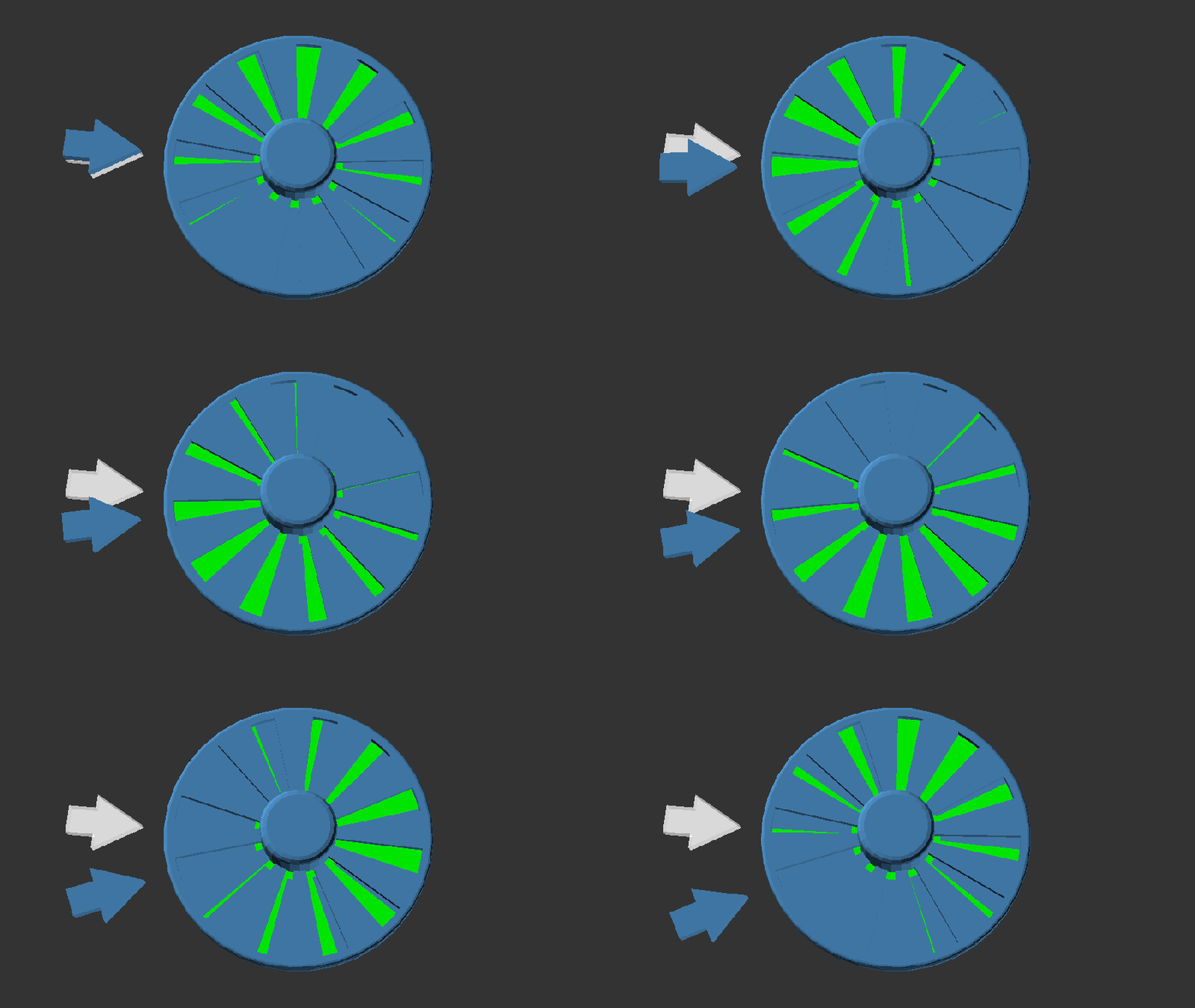
 [Jack]’s solution is a Vernier indicator for the extruder. Even the smallest movements of the extruder motor’s shaft are made clearly visible by such a device, as shown in the header image above. Vernier scales are more commonly found on measurement tools, and the concept is somewhat loosely borrowed here.
The usual way these lightweight indicators are attached is with a small magnet, and you can read all about them and see examples here.
This new design is basically the same, it simply has a background in a contrasting color added into the mix. [Jack]’s design is intended for the Bambu A1 printer, but the idea can be easily adapted. Give it a look if you find yourself yearning for a bit more visibility in your extruder movements.


I just used a dot from a paint pen, and its on a idler pully driven by the filament I don’t really care that much, besides the motor is going to move whether the filament does or not.
I am not really here to poo-poo, when we got our Prusa at work about ~8 or so years ago I was ready and willing to jump down the rabbit hole. but then I noticed (besides the thing being mostly printed, so it has the dimensional accuracy of an onion) that the limit switches were zip tied to a chromed & hardened rod slathered with grease, and its Z screws were coupled with lawnmower fuel line .. I kind of accepted that the “pretty darn good” results out of the box were not really investing a load of time fidgeting with it
my 5 year old ender sits out in a non climate controlled multi-use garage workshop, and from the factory the screws holding it together might have 15% thread engagement on the better end. With today’s slicers and profiles it can bang out some great parts at half the time.
So, yes have fun and knock yourself out doing mods and tweaks and finding that perfect setting. Just remember the clearance holes holding things with friction and luck, have at least a hundred micron of wiggle if not 2 or 3, and movement of your extruder is a good thing to know, as long as your filament isn’t broken.
One common way to attach such an indicator to the motor is to use a magnet to fix it on the motor’s shaft. But i’m wondering if the magnetic field produced by this magnet can in someway interfere with the motor’s internal magnetic fields?
Nah, the stepper has a very strong field concentrated in small gaps. Consider how hard it is to force it to turn when energized.
Do the motor’s internal magnets affect anything/are they detectable outside the motor? The effects are generally reciprocal: if you can’t see it, it can’t see you.
This looks like an interesting technique for making optical quadrature encoders without having to fight with precision mechanical/optical alignment.
Also inspiring thoughts of using moire patterns for other such sensors (maybe somehow introducing inherent wobble-reduction when the disks aren’t perfectly concentric?) or even 2d sensing (ala the original optical mice which required a special grated mousepad), but applied to more complicated systems like that hand-assisted CNC-router… Seems the precision could be increased tremendously in such a way over a simple camera…
hmmm….
(btw, why doesn’t HaD send me subscription updates anymore when I click “email me new comments?)
I don’t get those anymore either.