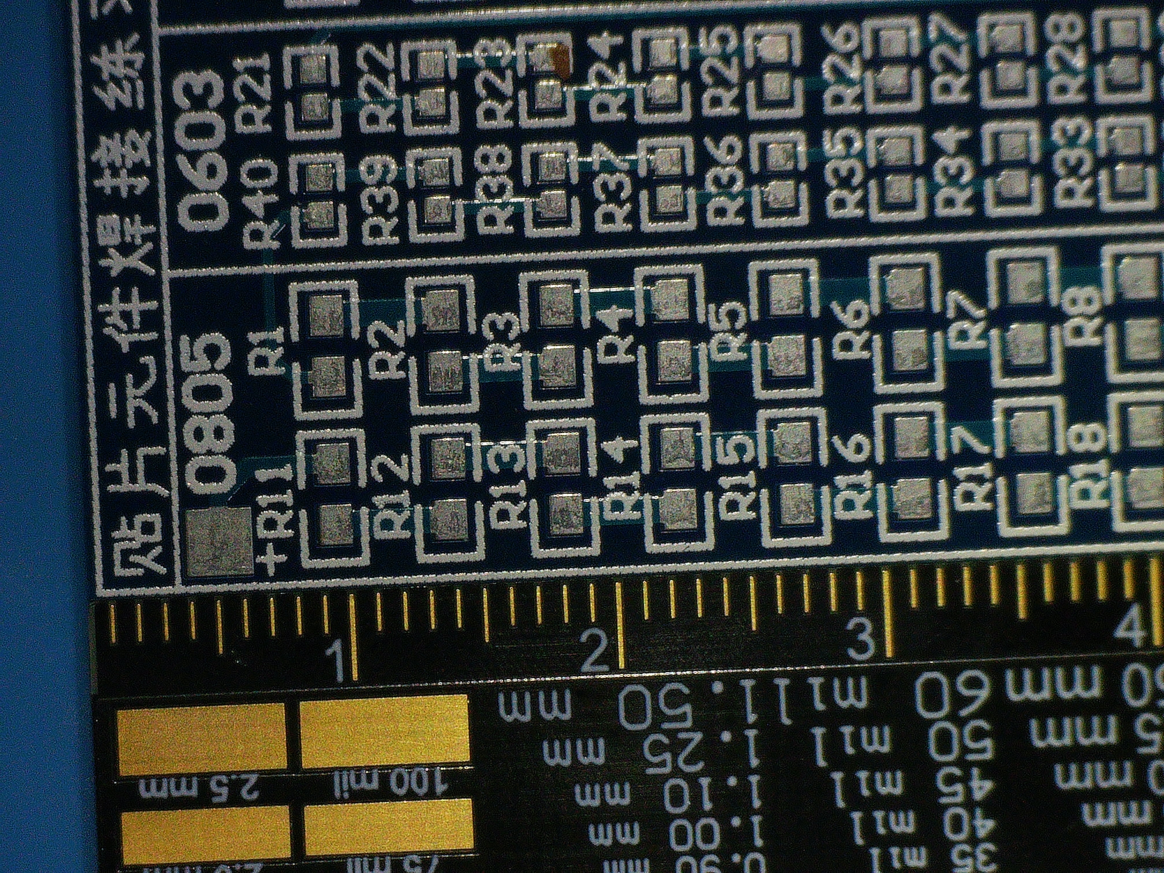
It used to be that only the most well-equipped home electronics lab had a microscope. However, with SMD parts getting smaller and smaller, some kind of microscope is almost a necessity.
 Luckily, you can get USB microscopes for a song now. If you’re willing to spend a little more, you can get even get microscopes that have little LCD screens. However, there are some problems with the cheaper end of these microscopes.
Many of them have small and wobbly stands that aren’t very practical. Some don’t leave you much room to get a soldering iron in between the lens and the part. Worse still, many cheap microscopes have trouble staying still when you have to push buttons or otherwise make adjustments to the device.
It seems like every time a new generation of microscopes aimed at the electronics market arrives on the scene, many of the earlier flaws get taken care of. That’s certainly the case with the Andonstar AD409-Max.
Sum of its Parts
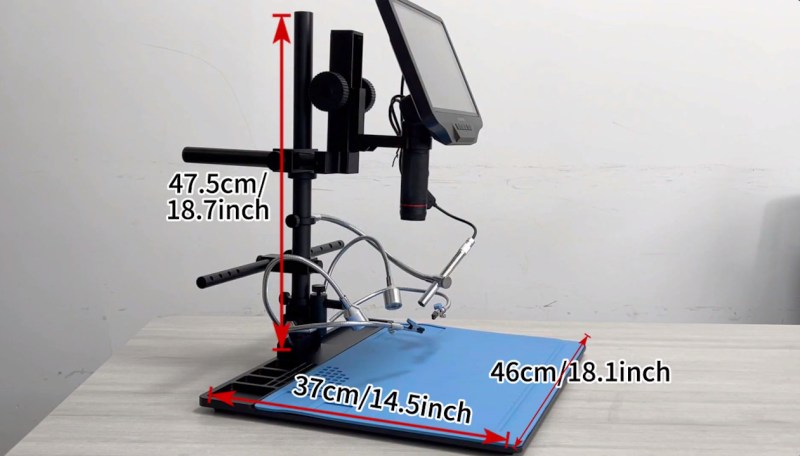
While the microscope looks a lot like many other Andonstar microscopes and, indeed, a lot of similar devices, you’ll immediately notice the work area under the microscope is huge and covered with a silicone work mat. We’ve put together a short video about the microscope that you can find below, followed by the promotional video from Andonstar themselves. That video will happily point out the positive things. Of course, there are a few negatives.
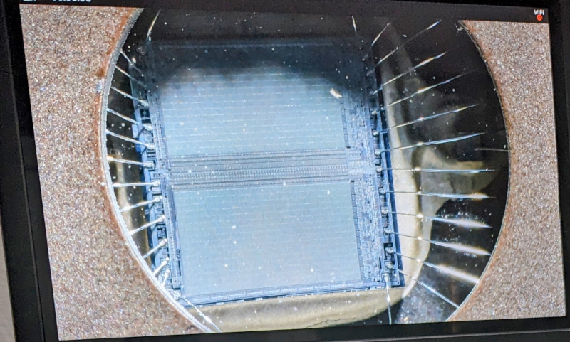
As mentioned in our video, the microscope is built solid and works very well. However, you can’t help but feel it is a hodgepodge of separate parts. The lights, for example, have their own switch. So does the endoscope. The camera itself has a WiFi hotspot (it won’t connect to your network, however). But when you load the phone app to download pictures and videos, you realize that the microscope thinks it’s a dashcam. The endoscope, with its little focus knob at the back, also seems like something of an afterthought.
These disparate parts lead to having a lot of wires. Of course you can easily 3D print some wire management clips or even use some zip ties to do it yourself. But the whole package would be a bit more impressive if the integration was better.
There are two mount points on the lens, one near each end of the lens body. We know some people like to mount at the bottom to get extra working distance, but you don’t really need to do that here. That mount is actually made for a ring light if you want to add one. The microscope might not be as stable as it will be when you use the mount closer to the electronics. However, do use one of the mounts. If you screw the ring in the middle of the lens body, you won’t be able to turn the lens to focus.
The Good News
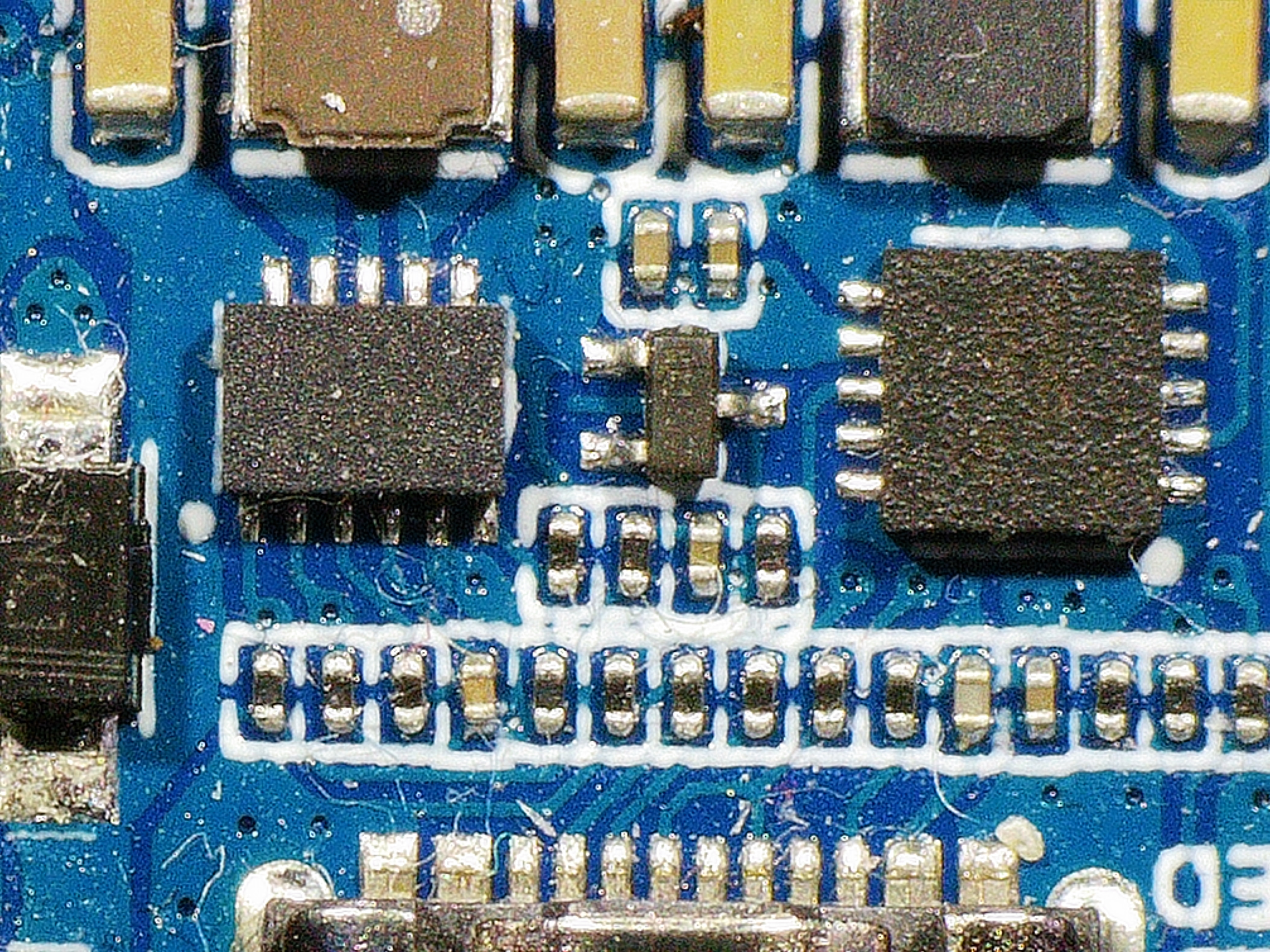
This isn’t the end of the world, though. The images look great, and there is a ton of room between the lens and the work surface. The video mentions “nearly two feet” of room. In retrospect, it is closer to 18 inches, depending on how much magnification you want.
Still, that’s plenty of space to work on things. What’s more is that, unlike some microscopes, there is a filter protecting the lens from solder fumes and heat. That and the silicone mat make it clear the microscope was made for soldering.
The lights are very bright. In fact, if you get what you want out of the light, it becomes very difficult to see. Unlike a ring light, you can adjust the gooseneck lamps to get just the right angle on whatever you need to see.
The microscope is well-packed and has a reasonable manual that seems mostly correct. There are several attachments for the endoscope, ranging from a short plastic tube to a little mirror for looking under things. If the screen is too small, you can always connect an HDMI monitor. All the required cables come in the box along with a USB power adapter.
Putting it to Work
There are less expensive alternatives out there. You could, of course, add a larger base to a cheaper unit. You may not really need the endoscope, the helping hands, and the tool holder. But if you don’t mind the roughly $450 price tag, this is a very serviceable soldering and inspection microscope.
Most of the issues are minor, like the cable management. For another example, despite the manual saying you can save default settings, it doesn’t seem to work. It would be nice if you could hot-swap the memory card, but you can’t. WiFi is a nice thought, but having to disconnect from your normal WiFi to connect to the microscope isn’t that convenient.
But for the main features, it works well. Sure, some people really like a binocular microscope. They, like anything else, have plusses and minuses, too. Do you have a favorite microscope or other magnifying device for soldering? Or are you lucky enough to have eagle-eye vision? If you do, just wait… you’ll see. Parts are getting smaller every year and your eyes seem to get worse every year, too.
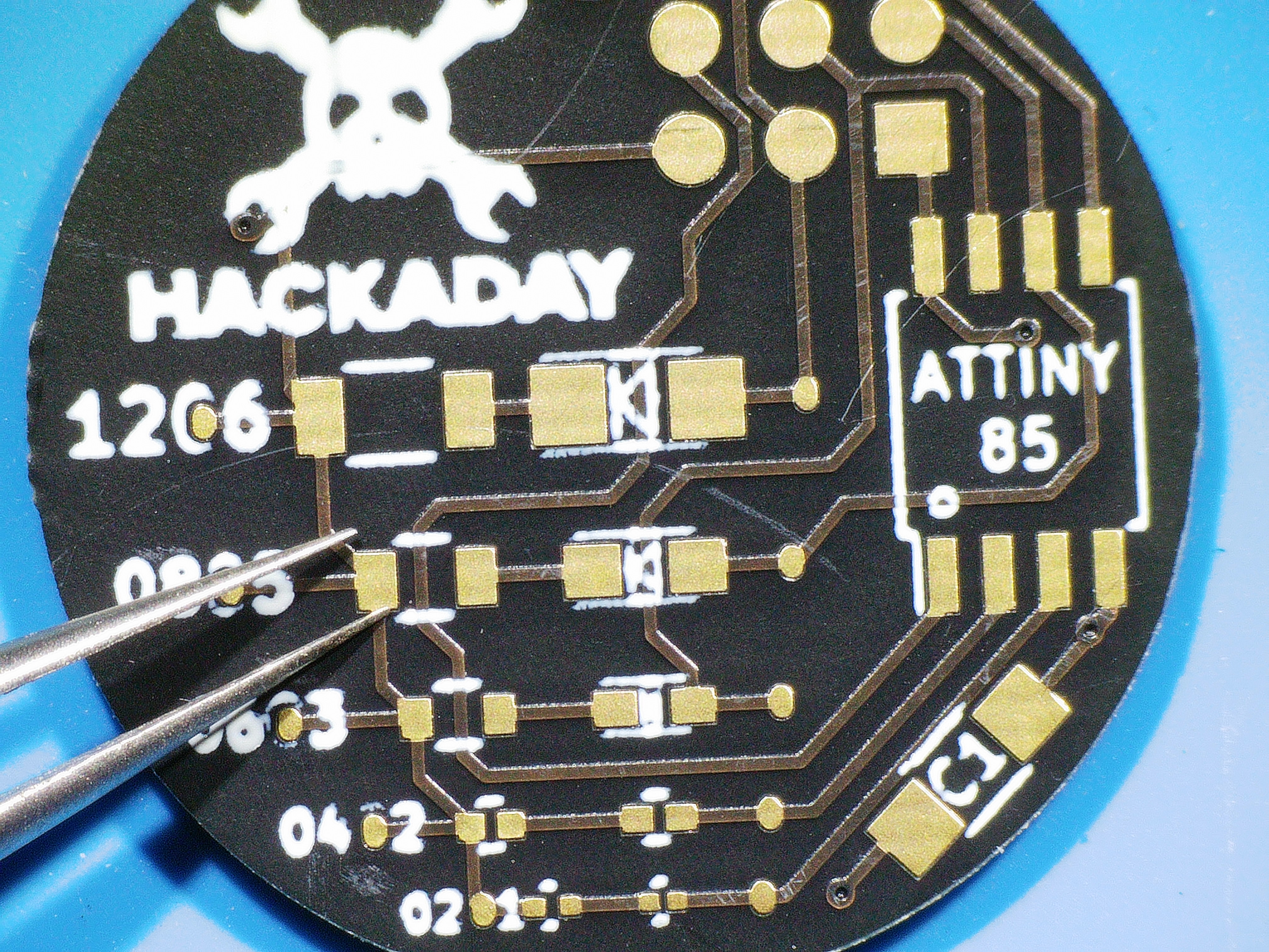
The video below shows a little bit of soldering of the SMD challenge board that we use every year at Supercon. Having a microscope is, of course, cheating, but at least we didn’t use a nice soldering iron just to be a little fair to everyone who’s had to use our terrible setup in the past.
You could mount a commercial ring light on the lower lens mount, or why not roll your own? You might not need as many upgrades for this rig as you would for a cheaper microscope.


The linked manufacturer refers to this product as including an endoscope. When exactly did the word “endoscope” get coopted by the electronics industry? I recall these camera-on-a-cord devices as fiber-scopes Because endoscopes have historically indicated a medical device. At-home colonoscopy anyone?
Streams have historically indicated with continuously body of flowing water, but now it means continuously transferred data too. Language changes over time.
Water, or air, or lava, or ice, or anything that… streams. Yes, including data. Nothing new here, nothing changed.
Technically, an endoscope is merely something with an end-mounted lens and imager. Even historically, they weren’t all flexible; some were more like a periscope without the final mirror.
And, from the other angle, many of these “tabletop microscopes” actually started out as cheap medical displays; the fiber imagers were by far the most expensive part, but simply substituting an appropriate lens stack made them useful to a new market, and earned their makers a few extra bucks. Although, not enough bucks to pay for updating the manuals and marketing materials ;)
Maybe I need a microscope buying guide. I’m guessing you wouldn’t have bothered to review it if it was grossly overpriced. But I don’t really understand what this over the $35 and $50 ones that is worth the extra $400.
I bought the cheap ones first, and had to go back for the more expensive ones. You don’t have to go for the $400 ones, there are very good ones at midpoint prices, as well.
I bought an AD407 from Amazon, myself. The stand is helpful to get you started on day one, but it might be easy to rig up a better mount for your particular need, once you have enough experience to know what you actually *need* :)
Without having played with the AD409, I really can’t compare them, but the AD407 was definitely worth the $200 to me.
Many of them use standard adaptor threads, allowing you to screw adaptor lenses (or filters, I guess) onto them. I used a nice gain-reducer so that I could fit more of the board in the field of view. This allows for quite rapid soldering of the larger SMT components, and you can always remove the adaptor if you need higher magnification.
I used the XT30WAB 30mm 0.43X Wide Angle Lens, which is not in stock anymore, but there are other options. That particular lens worked unexpectedly well as a field-flattening lens, not simply functioning as the gain-reducer that I had been expecting.
Most of these seem to have HDMI-out, and I REALLY recommend using them with a spare 27″ or larger display, if your vision isn’t the best. The onboard screen isn’t bad, but a large-format monitor suddenly makes everything but fine muscle control *easy*.
A few of them can take snapshots or short videos if you insert an sd card (this feature is often buggy, and may routinely blank the card for you, even if you didn’t want to do that). In every case I’ve personally seen, the snapshots are higher resolution than the HDMI output. Sometimes that’s useful, sometimes not.
It’s seriously worthwhile to consider rigging up a white-light LED ring (and maybe some programmable RGB LEDs). For some things, you’ll want shadowless light, but for others, you want a diagonal shot to give you some virtual depth perception. Using different colors from the left and right sides also helps in tricky cases by reducing the position and depth ambiguity. You can narrow or broaden the fov by moving the lens, but it’s not always possible to get the fov you need this time, while also getting the clearance you need for your tools. Variable light options can save the day, here.
Having seen both sides of the spectrum, it usually comes down to optics and working distance (both can make or break a microscope when used for soldering). There are also a few bells and whistles that while not necessary are really useful, like removable polarizer filters and hdmi output so you can connect a monitor. Also I’d spend a little more for a rigid metal base and stand, way better than faffing with plastic.
I got myself a used Mantis. Although entry level, never looked back to my wiggly USB microscope.
Would you also need a webcam buying guide to understand the difference between $15 1080 FULLHD Amazon special and $300 Sony A5000 with a hdmi capture dongle?
In my experience, the cheaper ones (USB) have a huge latency between what you see on the screen and what is really happening under the lens, so those should be avoided as you cannot work with those.
My first one was a second hand CCTV B/W camera with swapable lenses, but that was limited to a coax AV video output and poor resolution, but still workable.
In the end I bought a microscope camera with a high magnification lens which has a HDMI output, and have used that for the past eight years with a 23″ screen. I 3D printed a stand and made the illumination using an LED ring, that sits around the lens and that one provides more than enough light.
The total cost of this solution was less that $100 at the time, and I can easily solder 0201 parts.
The depth of field as you might expect is fairly limited, but not really a problem for most components.
I can second the latency problem with the super cheapies. It makes real-time use like soldering tremendously frustrating.
And don’t underestimate the quality and stiffness of the stand either, because it determines if focusing is easy and a one-off, or a difficult continuous maintenance chore.
I haven’t tried any of the “good” modern scope cameras, though. I went with a nice old used optical stereo inspection scope. I had to retrofit some good lighting, and I lose one eye if I want to take video, but it was trivial to make a camera adapter for a point-n-shoot.
The stand, the glass, and the focusing rack are absolutely rock-solid, though. Instead of having another screen on my desk, it projects the images directly onto my retinas, which is an acquired taste. It’s a 1990s experience, but a good one.
Could it work as an inexpensive CNC mill if used with a Dremel?
OK, I can see what I am doing with this but my hands aren’t steady enough. Any solutions?
In my experience bracing you hand(s) on a steady base can do wonders. Practice also helps.
Eliminating excessive caffeine is another tip.
And this may sound dumb, but in my personal experience just taking a deep breath and centering on the task can eliminate “yips”.
Cheers.
Reflow process is easier than hand-soldering, because you get many tries at placing the parts. Or you can even use a rig like https://blog.phdev.fr/?p=172&lang=en
Though a pretty good solution is to order most parts preassembled by jlcpcb, and if there are a few you need to add or some bugs in need of fixing, that’s more manageable than soldering the entire board.
Just steady your hand by keeping the wrist onto the working surface, and plenty of practice. Fine motor skills are hugely valuable.
As others have said: anchoring, coffee, breathing (or not).
But also, a good steady microscope / loupe actually helps your hands hold still. Something in the hand-eye coordination scales with magnification, in my experience.
Hi guys,
I just received my AD409 Max ES and getting it to work. I tried to change the resolution to 2560x1440p or 2880x2160p. The system accepts the setting but the real resolution does not change.
I tried internal monitor (knowing that it is limited to 1280), HDMI and camera output via USB. The resolution on the external connections is always 1920x1080P even if I switch to a lower resolution.
Any thoughts?
Best regards, Tim.