Mechanical switches are pretty easy to understand—the contacts touch, the current flows, and Bob is, presumably, your uncle. But what about soft switches? Well, they’re not that difficult to understand either, as explained by [EDN].
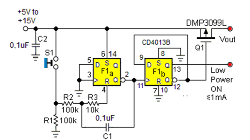
The traditional softswitch takes input from a momentary single-pole pushbutton and lets you press to toggle power on and off. This operation is easy to achieve with a simple flip-flop constructed with old-school logic to create a “bistable” circuit. That means it will happily remain stable in one of two states unless you do something to make it switch.
So far, so simple. However, you’ll need to consider that a simple mechanical pushbutton tends to have an issue with the contacts bouncing as they come into contact. If ignored, this would see your softswitch rapidly flicking on and off at times, which is no good at all. To avoid this, you simply need hook up an RC network to smooth out or “debounce” the button input.
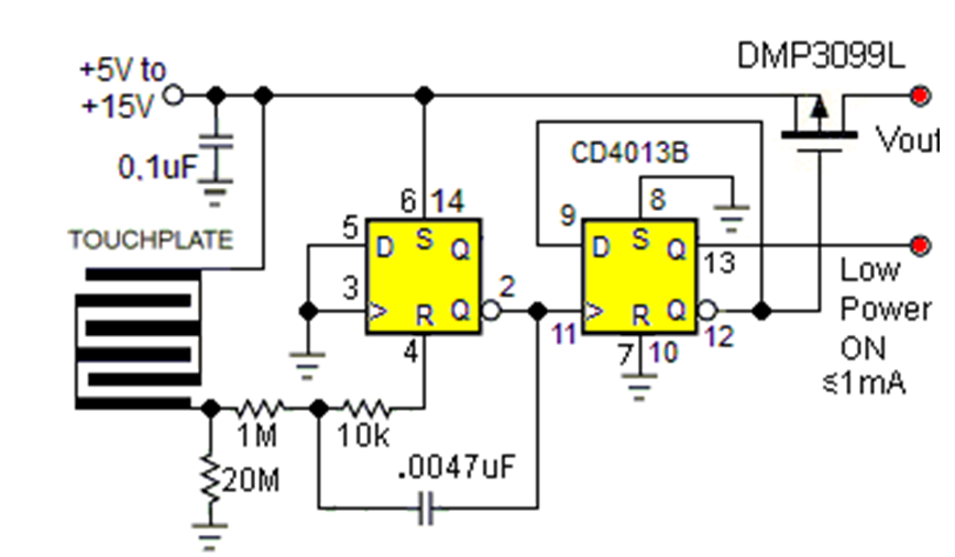
Read the post for the full circuit dynamics, as well as how to make the system work with a touchpad instead of a pushbutton. It’s rare to construct such elements from raw logic these days, what with microcontrollers making everything so easy. Still, if you want or need to do it, the old techniques still work just fine! There’s more than one way to solve the problem, of course.


Quiescent current…
Less than 1µA typical.
Ignore the CD4013B in the schematic, HEF4013 / HCF4013 are 30 µA worst case across temperature, with 1 µA max (0.02 µA typ.) at +25°C.
Why not use the ubiquitous 74HC74 dual D positive edge triggered flip-flop with asynchronous preset and clear? Here ya go: This Texas Instruments SN74HC74N in a 14-PDIP package is $0.88 each in unit quantity ($0.40 each @ qty 5k) with 5,564 in-stock ready to go:
https://www.digikey.com/en/products/detail/texas-instruments/SN74HC74N/277248
Can be done with just one 555.
https://www.555-timer-circuits.com/flip-flop.html
No, no no. The right way to give us that information would be: ” I could have done that with an 555…” like a real hackaday-snob. and don’t forget to start with Pfff….
:-)
@macsimski said: “…and don’t forget to start with Pfff….”
If u gonna do it – do it right, It’s Pffft not Pfff.
see? thats the spirit!
5V input? Is it the year 2000?
3.0..4.25V
AFAIU this is not meant as a logic level input or to switch power at the logic level, but rather to switch power at the voltage level of the wall wart (e.g. 12V) that powers the step down regulator which in turn powers your 3.3 V logic circuit.
5v is proper TTL standard, I see no problem here.
Many circuits also commonly used up to 12v (13,8v) or 24v (25v) for operation.
The RS-232/V.24 specification uses ±12v (or ±15v), with a limit of ±25v.
So I assume you don’t use USB-C with PD or QC, to charge high voltage batteries?
[For the younger generation]: for the same load…higher voltage=less current, less current=thinner wires, thinner wires=lower cost.
Putting a 14-pin TTL/CMOS chip or MCU on a PCB is the same amount of design work. With TTL/CMOS there is no coding for me to do, when I only need soft-switching for a single button…
CMOS quiescent current is negligible, for all but the most low-power designs. I Fail to see any downside to this circuit. There are no silver bullets in electronics. You use what makes the most sense, for that particular application/project, at that particular time. Brilliant engineers have created absolutely brilliant circuits over decades, so why not use them? You shun the circuit because it is “old”?
Younger hackers might not remember SCSI, but Ohm’s law is still cool…
Nice example, but it perpetuates the same old dumb UI problem: the same button and the same action performs two very different functions depending on when you push it. Why do people persist in making user-abusive interfaces like this?
+
Did I miss something when reading the article, or we calling toggle buttons “user-abusive” now?
That’s the point. It’s NOT a toggle. It’s the same button that looks the same, feels the same, but does different things when you push it, depending on when you push it.
It reminds me of conversations I had with Jef Raskin about state in user interfaces.
A toggle button has state, be it an electronic latch or a mechanical latch. As a user I either have to look at the state before operating it, or risk trying to track that state in my head.
With a toggle switch, I can at least feel the switch besides looking at it. And I use an up-motion to turn it on and an down-motion to turn it off. (3 position switches are sub-optimal, use a rotary switch please)
And then, after he’s gone, the Mac Mini comes out with a pushbutton on/off power switch on one side side, and a power LED on the opposite side, facing away. And it has an indeterminate time, sometimes lengthy, between pushing the button and getting an observable change of state. Seriously, Apple, you’re supposed to be the ones good at this.
+1 His book on Humane Interface should be read by anyone working on HMI, etc. I always forget one of his 3 principles. Modelessness, Monotony, and ???? I don’t recall if they are in the book.
The modelessness kinda excludes any sort of a menu system. Strictly speaking, your “ok” button does a different thing depending on your position in the menu tree.
Yet these kind of interfaces are obvious after you learn the basic idea. Not everything needs its own button.
Whoa there… Hold on.
I agree with the multiple use stance, probably more strongly than you.
But this? Toggling a single function on and off is NOT part of that problem.
If you are going to argue something, at least take some time to understand it
The problem is you need to know for sure which state the system is in. Not always possible.
Having separate on and off buttons never goes wrong. better yet, a rocker switch,
Failing that, at least a LED to indicate current state unambiguously.
It’s rare to have a device where the state of being on or off isn’t obvious from the fact that it’s doing something that it’s supposed to be doing.
There are devices where the power button is more like an interlock switch whose purpose is to prevent unintended operation. That’s when you need the indicators that the device is “armed” but not yet doing anything – but then you absolutely need to have a reliable indicator anyways.
Sadly not as rare as it should be.
Pretty much every modern phone or tablet has some delay between pressing the power button and something happening to indicate it is booting. Worse, it requires some arbitrary minimum button press period to register, so you don’t know whether your button press registered for several seconds, then you try again when it didn’t work the first time. Then you press too long and end up hard-resetting it. And the next device has different timing constraints for these actions.
Similar are the godforsaken power buttons on laptops that have the LED under your finger, so you don’t even get acknowledgement until you move your finger out of the way.
Even worse are the ones like car radios that buffer power button events, or inhibit their operation in some conditions (like when in reverse gear).
Nonsense like this is laziness from the designers, and is frustrating and even unsafe for users.
Really, it doesn’t need to be this way.
What you’re saying is, you need an immediate confirmation that you’ve pressed the button and activated something, so you can then wait for that thing to happen.
Sadly this decouples the logic, so the indicator no longer indicates function. It’s like the Three Mile Island case where the indicator light for the pump indicated that the switch was turned on, not whether the pump was actually pumping. You kinda want to avoid such designs.
if push on / push off is too mentally challenging for some, then they’re not my target demographic. Many things could benefit from a ‘You-must-be-at-least-this-smart-to-operate’ barrier
My only user interface is a JTAG header. Keeps the riff-raff out (or in, depending on your POV)
You might be surprised how adrenaline affects members of your mentally-superior target demographic when they are desperately flailing for the emergency kill switch while being wound arm-first into a large machine tool.
The emergency kill switch on a device that should have it is NOT the same as a power button. It should be a big red button whose use may mean you have to do something to restart the machine, rather than just pushing it again. It or they should be located within reach of the place or places where you might encounter an emergency, even if the regular controls extend away from there.
It’s just as bad to have way too many separate controls so that you can’t find the one you need. Like if you had to use all different sets of directional buttons for the same function in very nearly the same conditions.
I’m gonna take the arrow keys off your keyboard and replace them with a button. You’re welcome.
No, you’re gonna act superior for having been able to misinterpret what you read. The point is that it’s bad design to randomly require the same inputs be given on a different set of buttons that’s not any better than the original way.
If I can enter a number in three text boxes using the numpad, but the fourth box only lets me enter the number using the top row numbers, that’s stupid. It’s fine if there’s more than one button for something, the problem is when every hyper specific case only works with exactly the right button.
Like if you had a different keyboard for typing in italics and you had to go and pull it out and move over to it before you could italicize anything, and the backspace on that keyboard could only backspace italic letters while the backspace on the regular keyboard could only backspace regular letters. Just use the same button!
Having a confusing wall of switches and buttons is still vastly more preferable. The idiotic single rotary encoder or button interfaces that seems to be in fashion are extremely frustrating to use.
It’s the touchscreens that are really annoying; they mean a UI always gets simplified – lots of whitespace, a few clickable buttons, maybe a dropdown with a very few options, rarely a real menu or something involving clicking and dragging or double clicking or right clicking or hovering or all the other more advanced expressions a mouse can do.
As for much simpler devices, at least a number of the rotating pushbuttons can also do directional button input. If you just need to scroll through menus and then select things and change them, that’s not the worst. The slowest part of using the set of actions {[↑], [↓], [→], [←], [Ok/Yes/Set], [Cancel/No/Back]} is the scrolling, and a wheel helps there.
I’d refine that a bit; the problem is not when you push it, it’s the ambiguity around what happens when you do. If you have a UI toggle marked “on” and “off”, is it telling the current state, or the consequence of your action? In the physical world you run into this problem much less.
Paul – I am with you on that point 100%.
I recall in the bronze age of the industrial design (which would be maybe 1950s through 1970s) the “every function has a pushbutton/dial/rocker-switch” came to its final and most productive apex in the designs of the nuclear power stations’ control rooms. The rest, say, consumer wares, was already mostly in the process of reducing the number of control widgets to its minimally usable set, while some specialized industrial places (say, flight control towers, or aircraft carriers’ fleet command decks) were still going through the growing pains.
What we have now is the legacy of all those combined, stone age thinking that brought bronze age, iron age that culled some of the bronze age thinking, but made it much worse by too much pointless sophistication, incessant refinement of the iron age thinking into atomic age thinking, etc. It is a mess to put it bluntly.
The sad examples of such, classical LCD clocks, suffer from this still, usually they have two buttons to operate them, sometimes three, but they suffer from the same ailment – no simple way to dial anything, unlike the analog clocks/watches that always had at least ONE dial/knob (which would set the time … the moment one pushed or pulled the knob, it WAS the equivalent of pushing the SET button on the LCD clock, and rotating the said knob would be the equivalent of “fast forward/backward the time setting”). Analog clocks/watches had the simplest and most intuitive connection – rotating the said knob corresponded to the rotating hands on the clock/watch dial. Whoever (during the late iron age) severed that connection made our lives pointlessly complicated.
I think you can make a D flip-flop with 3 transistors. Certainly you can make a discreet button toggle circuit with relatively few components. But there is probably not much cost savings using discreet parts versus an IC like 74HC74, 74HC174, CD4013, etc.
For a multi-use project. I think I would lean towards a gated JK flip flop. like CD4096. You can construct a radio button style interface with that. You can also, with some supporting logic, load/save your settings or have multiple functions assigned to button. It gets hairy really fast because you need a latch for the button/LED “interface” and a latch for each thing you actually want to control. And it turns out the low-end PIC microcontroller does a better job at a fraction of the price when it comes to state-heavy designs.
There are single-chip, robust solutions for this that handle the debouncing and sequencing, uP interrupts, etc., like the LTC2954. Too bad it’s fairly expensive.
A really nice, simple, cheap way to handle this is with a PNP switch on the power line: Zero quiescent draw, a pushbutton starts the system. To turn off, you tell the microcontroller through the UI to turn off, and it does a controlled shutdown.
It’s famously used in the cheap and cheerful “component tester” device, like this one: https://oshwlab.com/hassan.mahmoud.momen/Component_Tester-ZV7HgeO0Y Discussed previously in these HaD pages, but it didn’t turn up in a quick search.
That’s a great way to do it: Zero quiescent power drain when “off”; a single unambiguous “ON” button, instant “on” indication via a LED, a different user action to turn off, and a microprocessor-driven controlled shutdown (so no random shutdown during, e.g. a disk write). It’s a perfect solution.
There’s a more easy-to-understand schematic at this location in this video: https://youtu.be/4Xsg8lpP75s?t=611
What if the controller crashes and you need to power cycle it?
For instance, what if your battery runs down and your mcu browns out, then never shuts down the power?
Watchdogs. Reset buttons. Battery voltage monitors. Hard power switches. Pull the batteries. Unplug the thing.
Really, it doesn’t need a genius.
All of those require either additional hardware, or are subject to the same software crashing issues, or require the user to pull the device apart to remove the battery. Remember we’re talking about battery powered stuff, so no external power plugs to pull.
So hardly a “perfect solution” if you then have to come back and fix these problems. A proper toggle switch cuts the power regardless of what the device is doing.
To a geriatric generation, Soft Switch means the Steve Wozniak circuits in the Apple II. A part (74LS154?) is used sort of backwards with address lines to data inputs IIRC. Using the fact that the LSB of addresses alternates 1 and 0 as it is incremented. The part latches that low bit value. Write to one address and get 0, and to address+1 and get 1 on the output. One chip gives 8 of these outputs I think without checking a Red Book.
It is one of those nice features of memory mapped I/O that I miss a lot in this age of serial everything. No configuring or “drivers” or “registers”. Just a constant you use as an address for a write.
An even simpler switch circuit I particularly like using even less components, just one NPN and one PNP 3 resistors and a capacitor. It’s a bit hard to explain, but below is a plain text description that you can paste into falstad circuit simulator. You might need to increase the simulation speed or lower the capacitor value to see it working well, it’s debounced so can appear to react very slowly otherwise, but is quite responsive in real life.
$ 1 0.000005 382.76258214399064 50 5 50 5e-11
f 432 304 480 304 32 1.5 0.02
f 336 192 400 192 33 1.5 80
r 272 208 272 304 0 100000
r 272 128 272 208 0 10000
c 272 304 272 384 4 0.000001 4.99778586854946 0.001 0
w 272 304 288 304 0
g 272 384 272 416 0 0
w 272 208 336 208 0
w 272 128 400 128 0
w 400 128 400 176 0
w 336 256 480 272 0
R 400 80 400 32 0 0 40 5 0 0 0.5
r 400 224 400 304 0 10000
w 432 304 400 304 0
w 480 320 480 384 0
w 480 384 272 384 0
w 480 272 480 288 0
w 400 224 512 224 0
w 336 208 336 256 0
r 512 224 512 384 0 10000
w 480 384 512 384 0
w 688 224 512 224 0
162 688 304 688 384 2 default-led 1 0 0 0.01
w 512 384 688 384 0
r 688 304 688 224 0 1000
368 272 304 192 304 0 0
370 400 80 400 128 3 0 0
w 336 192 336 208 0
w 400 208 400 224 0
x 701 308 754 311 4 24 Load
s 288 304 400 304 0 1 true
x 300 332 400 335 4 24 Push\sSW
Can anyone tell me what package (if any) was used to create that circuit diagram please? I have seen the style before (most notably on “Harry’s Homebrew Homepage”).