
When PCI-SIG introduced the 12VHPWR power connector as a replacement for the 6- and 8-pin PCIe power connectors, it created a wave of controversy. There were enough cases of melting GPUs, PSUs, and cables to set people on edge. Amidst this controversy, [JayzTwoCents] decided to do some scientific experimentation, Mythbusters-style, specifically: do these 12VHPWR (or the 12V-2×6 successor) wear out upon hitting the often cited 30 mating cycles? If this is the case, it could explain why people see wildly different current loads between the wires in their GPU power cables. Perhaps reviewers and hardware enthusiasts should replace their GPU power cables more often.
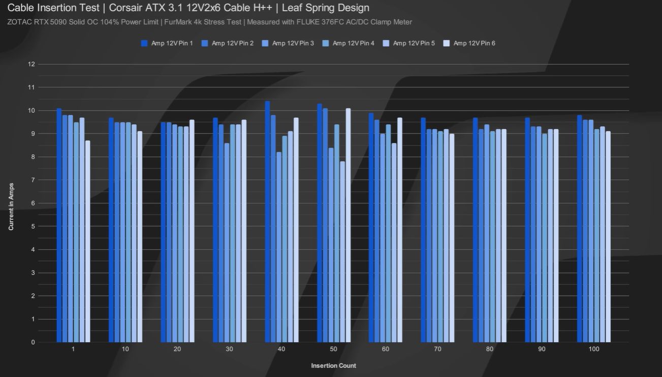
Like many Mythbuster experiments, the outcome is less than clear, as can be observed in the below graph from one data set. Even after 100 mating cycles, there was no observable change to the contact resistance. One caveat: this was only performed on the GPU side of the connector. The first cable tested was a newer connector type that uses a single-split leaf spring design. Initially, most of the 12VHPWR connectors had a double- or triple-dimple design to contact the pin, so [Jayz] tested one of these, too.
The amazing thing with the 2022-era cable that got pulled new out of packaging and tested was that it looked terrible under the microscope in terms of tolerances and provided a very uneven load, but it got better over time and also lasted 100 cycles. However, it must be said that ‘lasted’ is a big word here, as the retention tab wore off by this point, and the connector was ready to fall out with a light breeze.
Perhaps the ‘mating cycles’ specification is more about the connector as a whole, as well as how the connector is (ab)used, at which point good (long-term) contact is no longer assured. Along with the different types of Molex Mini- and Micro-Fit style connectors, it’s worth keeping an eye on with more applications than just GPUs.
We have certainly seen some burned connectors. Particularly in 3D printers.


Why reinvent the wheel when there are welding cables with connectors good for at least 250 amps.
Because some people will then “weld” their GPUs by connecting them to their welder instead of “new” PSU…. ;-)
…Wrong! I would use my desktop PSU to run a TIG ;)
+1
Because of specific application requirements you are overlooking? Why would it be a good idea to “permanently” weld computer components together in a system that is meant to be easily upgradable and serviceable? Why not just pot the whole thing in epoxy while you are at welding all connections?
He is not talking about permamently welding components, he is talking about using connectors used in welding machines, which are rated for very high currents, exceeding the requirements for GPUs by a very large margin. Which might be overkill, to be honest: 250 amps at 12 volts is 3000 watts, an insane value for a silicon chip.
Ah, sorry I misunderstood. I’m sure there’s a middle ground, I know companies like molex and semtec definitely make high current connectors for card edges and blade style connectors.
Running parallel cables for higher wattage power is never a good idea. Cables will carry different current for a variety of reasons.
Together with connectors and cables that are only rated 1% higher than there planned max current.
They didn’t: this connector is just a specific keying of the Molex Micro-Fit connector, which has been in use for decades. Just as the commonly encountered PCIe12V, EPS12V, and ‘ATX’ connectors are Molex Mini-Fit jr.
XT90 would be perfectly suitable for this, they are rated for 90 A continuous (1080 W at 12 V) and 1000 mating cycles. They are a very simple two pin design that is difficult to not insert properly. If they need extra communication or sensing pins then they can adapt the connector like the xt30 connectors with two smaller extra pins on the side for data. They would be easier to insert properly, tight once inserted and you don’t need to worry about uneven loads since it would only be two power wires.
The only thing against them would be that they are essentially a friction fit but I am just mentioning them to prove the point that high current connectors with high cycle lives are common, cheap and better than what they have come up with.
They use 12 power wires to carry up to 600 W without much margin of safety. Why? Why when there are perfectly suitable connectors that can handle much more current with only two pins and wires?
I think we need a full redesign of modern PC PSUs and connectors, there is little reason other than compatibility to use the connectors we do. We could use more suitable connectors with fewer pins and wires to run. Once you get to the point of needing multiple connectors then something is wrong, like multiple CPU power connectors, up to 4 GPU power connectors for a single GPU, etc. A new standard should be made and it should be as simple as possible using proven connectors. In theory all you could need is one pair of power wires for the CPU and motherboard and one pair for the GPU, although it could be useful to have two data pins along with them or even sense pins for measuring contact resistance or current.
The true core of the issue is getting the power into the relatively thin layers of copper in the board. An xt90 connector would not spread the power into the power plane of the PCB. The rating is also deceptive xt90, as it’s based on a free air trise rating of far greater than the standard iec 30c t rise at ambient.
The current power connectors fail due to fretting corrosion on the high normal force tin contacts which is incited through thermal cycling and a lack of free tin in the contact point. As the cycles increase, the tin wears and then is unavailable to maintain an electrically stable connection. Initial contact resistance is irrelevant. Run 1000 thermal cycles and the deltas in contact resistance will become evident. These connectors are used in a current sharing arrangement. The crimps and wires have different resistances. As one contact’s resistance increases slightly compared to the others, the other contacts carry a higher load and then degrade, which repeats the process until multiple contacts are degraded and then you have thermal runaway on a contact which produces a “thermal event”.
Google fretting corrosion.
Don’t mate and unmate this connector any more than necessary. The tin is wearing away every cycle. Bad things will happen eventually. It could take months or a year, but the initial resistances are unlikely to reveal the impending issue.
I’ve seen some hot swappable server power supplies that route the main power through a couple big gold pads (or a bunch of smaller ones) on either side of a normal looking PCB a few inches wide, and I have seen at least 12V 200A on something rated for like 94 or 96 percent efficiency this way. Seems like for 600W you could make it about an inch wide and add some locking around it. Guess you’d have to deal with the cable end being live all the time if your sense that enables the power is on the gpu input and not the psu output like it is in the servers. They already have to put gold contacts on the PCIE on the other side of the PCB though, so would that sort of thing not work here? Although maybe I answered my own question, who’s going to agree to all use the same thickness pcb?
The problem is that changes in this space are near impossible to carry out, and manufacturers tend to cheap out as much as possible. There are in fact consumer configurations that can exceed an XT90, so I think we need a 24V rail for the new generation of high draw devices.
insert xkcd about 15 competing standards
Companies protect their products with their brandnames, if you use their property, the sue you. That is the stupid side of our world economy.
Did a quick search for “high power pcb connector” found multiple similar designs for the (automotive) industry:
https://vehicle-electronics.biz/content/phoenix-connectors-rise-tti
Phoenix connector, used for ac/dc power, as well as audio and other av hw (data liner, relays etc). Pretty durable, reliable and not pricey. But eould take more space and ppl don’t like to respec/redesign.
They don’t like it because it’s expensive. It requires new tooling and engineering hours, which costs millions.
It would be rare for a connector to break at exactly the rated cycle count, or even 4x that. It’s that some units will be worse off to start with, and then the problems usually only increase over use. If the manufacturer hasn’t just pulled the rating out of thin air, it is likely derived from statistics over a large sample of connectors, some of which broke earlier and some later.
I don’t know much about the GPU market size. In our business, if we have 10 parts per million failing in the field, we have VP’s shrieking like sirens, and we do ship millions of parts, and getting the long tail of failures down to <10ppm means 99.9997% of our parts can survive vastly worse operating conditions than our specifications would indicate.
Sadly most consumer electronics is not like that.
Based on how little safety factor they put into the actual current ratings then I wouldn’t be surprised if they failed right on.
There are a surprising number of common connectors out there specified with very limited insertion cycle ratings, SATA connectors, car ECUs etc. tend to have very low figures.
Basically because they’re designed to be installed and used until they fail, which the vast majority of items in the field are.
I think high current connector work only well and reliable if they made by a good experienced company and only if both parts made by the same company! And of course only if the people that use them have some experienced in look and feel when connecting.
For this reason I think this kind of connector are a wrong choice for the combination of current, user and a world where every company try to make anything as cheap as possibly.
Perhaps they should rise to voltage to 42V. There a already POL-Converter on the cards.
or just use the whole card edge for power. some server power supplies deliver power via a full copper pour on the edge of the pcb and connect into big connectors much like old 5.25 drive data cables. dozens of Pins for contact and far more current delivered. much more robust too.
The issue is standardization. It is a good thing, but when hardware power requirements increase significantly as they have with high end GPUs, the standards have not kept up with the hardware. Standardized connectors for PC power supplies need to be updated so a new more robust connector becomes the new standard. Some fault could be put on GPU manufacturers for pushing out hardware with power needs that the standard connectors can’t handle.
I design automotive ECUs that easily draw 150A.
You know how many pins in the connector we use for this?
ONE!
And if we use two of them for higher reliability, every one is heavily monitored, and we have a switchover circuit and thermal fuses.
Using a lot of weak parallel pins for high currents, without monitoring and load balancing is the worst design you could imagine. The outcomes are as expected.
Why use many pin when one big pin (and a frame ground) just as good
Also why the heck is a 12v ECU sucking down 1800 watts? Or is this an electric motor controller
Ignition coil drivers.
I’m guessing that’s one of those “technically it peaks at 1800w for 1.3 microseconds” situations. I don’t have any 150 amp fuses in my fuse box, certainly not for the ignition coil drivers… Maybe a fusible link for the starter motor but that’s it
FuelTech, Haltech, Motec and many others all use AMPseal 24 or 36 pin connectors. They each use 3-4 power and ground pins, instead of one large power/ground conductor.
Surely these major ECU manufacturers have not committed to “the worst design you could imagine”.
I think RC battery technology could be used to connect power, I mean the connectors and wiring from that. These are capable of high currents at low voltages. And reducing the number of wires to just one pair, with thin stranded wire, making them both high tolerant to current and be very flexible for easy cable management. Those inflexible and stiff wire harnesses could be part of connector failures.
Multiple wires will cause balance issues, depending on the resistance per connector contact, one will always be loaded more than all the others. Arcing within the connector will heat it up, and as the damage increases, so does the arcing and resistance, and it’ll be a runaway process, melting the connector as a result.
Higher voltage could be a solution too, but that would mean changing the whole psu too, that’s not going to happen overnight I guess.
I wonder if the high frequency power draw induces current in the connector as well.
as150u connectors are rated for more than enough amps, can take up to 6g wire, and gave 4 pins for data. They’re only slighty larger than 12vhp connectors. These would be a simple way to.solve this problem.
Sometimes the connectors are a case of planned obsolescence. Pinball manufacturers suspected that the first solid state games would have such a high lifetime, that operators don’t buy enough new games. So they used connectors with a specified insertion cycle count of 5-25 to make sure the game would not get too many rotations between locations before intermittent faults due to bad connectors. Today, collectors of old game machines have a first task to replace most connectors before even trying to fix wear on playfield etc.
Is there a source for this? Sounds like you would quickly get sued for such a thing, and you’d have people with crimpers and wire strippers just removing the connectors and adding cheap automotive ones. Pinball machine maintenance involves a lot of DIY already anyway
Planned obsolescence is everywhere in appliance manufacturing, especially but not limited to consumer hardware. Oversight has been crippled so going after them is difficult. On example I’ve seen is mountings in a wet environment with cat aluminium brackets on stainless steel. It wears out just as the warranty expires.
Many years ago I worked on high current DC magnet power supplies. It was low voltage, high current (5Vdc at 200A) and used copper bus bars to distribute the power. THE best way for checking that the correct torque had been applied to the various fasteners was to measure the millivolt level DC voltage that was present across each node when the full 200A was applied to a dummy load. I would suggest that a similar method (4 wire sense) is applied when characterising these connectors as you can immediately determine the resistance of the mating contacts and see the change as a function of the number of insertions.
I think that a major part of the problem is the location of the connector. It might work right for the PCB layout, but for most end users, it’s in the wrong place. Completely the wrong place. If you build a PC with a glass window and want to see a nice clean computer without a bunch of wiring mess, then the connector and it’s cable are a huge annoyance. As a result, people try to find ways to hide the cable, by pulling it to the side, using zip ties to keep it tight. That puts strain on the cable and the connector. If you look at the card laying down, fans towards you with the PCI part at the top, the connector is now at the middle of the bottom. If they moved that to the top right, like several cards I’ve had in the past, people wouldn’t have to invent ways to hide the cable.
This feels like a phone manufacturer putting the USB-C connector in the middle of the screen or Apple putting the charging port of the mouse on the bottom.
This is a stupid connector design, full stop.
All the problems we saw with 12V-HPWR and all the problems we’re seeing with 12V-2×6 are a result of entirely predictable failure modes. Repeated insertions, uneven torque on the cables & connectors, handing by end-users who don’t have a background in electrical/electronic engineering, insufficient manufacturing tolerances, poorer-quality third-party connectors, no load monitoring or balancing on individual pins…
But no, it’s the user’s fault: “you didn’t plug it in all the way”, “you tugged the cables too hard”, “those third-party adaptors are bad quality”, and so on.
I refuse to believe that Nvidia does not know how to design robust, high-reliability connectors that carry high power levels. They’ve been in the consumer graphics card business for 40 years, they know what they’re doing.
Slap a couple of XT90 connectors on the card: there’s your new high-power GPU power connector spec.
You’re 100% correct. I would personally use as150u connectors, and 12vhp is just a stupid design. Every other industry uses larger components for higher power instead of more.
Connectors chosen for final development are wildly unsuitable for use in development – and vice versa – from what I’ve experienced. Something is chosen, there were more mating cycles than expected (0 vs 15) in manufacturing and then there are field failures. And all this based on the posit that serviceability wouldn’t be an issue either – so it’s not made to be fixed at any point – to reduce manufacturing costs.
i’m always impressed by how these low cycle count products don’t tend to be a problem for me. i mean, if you’re plugging and unplugging it every day or every week then you’ll run into troubles very quickly. but for usual usage… for example, i recently upgraded my CPU and the new one didn’t have a built-in GPU, which i didn’t realize meant that it would also disable my motherboard HDMI out. no problem, but i felt like i spent a whole day swapping CPUs back and forth trying to figure it out. the whole time worrying that the lifetime of a ZIF socket must be low double digits. but when i was all done and finally had it working, it worked out to i think 5 total insertions. and that’s 5x as many as most of the motherboards i’ve had. even when you have to work at it for a while, if the typical usage case is one insertion, it’s unlikely you’ll go much over 10.
get the same feeling from flash / EEPROM. like the PIC12’s program memory is only rated for 1000 programs…and i’ll sit there flashing it every 5 minutes the whole time i’m working on it. and i always feel like i’m wearing it out but i don’t think i’ve ever flashed any single chip more than about 50 times total. if you aren’t automatically writing to it then the time that you spend focused on breaking it just doesn’t really add up
Aren’t those small antenna connectors U.FL and IPEX4 limited?
Everything is – and the more mating cycles it goes through where it’s misaligned and forced makes it worse.
Well I’m glad I’m built better than that cable, definitely been more than 30 cycles lol.
So if the cable dies from too many mating cycles… Does that mean “death by snu snu”?
at this point it’s clear GPUs just need to be connected directly to the PSU via some solid copper bus bars, and machine screws. it’ll eliminate all of the fire concerns, and also provide mechanical stability to the card.
Molex is NOT for current. EE 101
Amass XT 90’s and silicone wire. Problem solved move on.
Totally agree. Use the right components for the job. GPU’s are NOT cheap! Just do it right
Maybe in the next iteration, the sense wires should be just that, to sense the voltage at the PSU.
The GPU can use that to monitor the voltage drop and determine the power dissipation.
Using multiple low current pins to carry high current with marginal safety factor is bound to end poorly.
Unless each pin goes through a separate sense resistor, the GPU has no idea of a problem until something is burning.