In a recent video our hacker [Electronic Wizard] introduces the 74HC595 shift register and explains how to use it to drive 7-segment displays.
[Electronic Wizard] explains that understanding how to apply the 74HC595 can increase the quality of your projects and also help keep the demands on the number of pins from your microcontroller to manageable levels. If you’re interested in the gory details you can find a PDF datasheet for the 74HC595 such as this one from Texas Instruments.
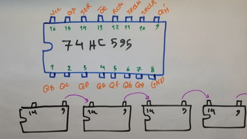
[Electronic Wizard] explains further that a shift register is like a small one byte memory where its data is directly available on its eight output pins, no input address required. When you pulse the clock pin (CLK) each bit in the eight bit memory shifts right one bit, making room for a new bit on the left. The bits that fall off the right hand side can daisy chain into another 74HC595 going out on pin 9 and coming in on pin 14.
[Electronic Wizard] goes on to extol the virtues of pin 13, the active-low Output Enable, which can be used to make sure junk doesn’t appear on your 7-segment displays during initialization. Also the 74HC595 can provide current itself which lessens the power demands on your micro.
[Electronic Wizard] covers how to use multiplexing to drive multiple 7-segment displays but notes the drawbacks of this method including large pin counts and high frequency flashing which, while invisible to the human eye, can become visible on some cameras and recording equipment making the 74HC595 a superior solution to multiplexing.
The bottom line is that using only three pins from the microcontroller you can drive one or more 7-segment displays. To learn more, including how to use the other pins and features of the 74HC595, be sure to click through to watch the video. If you’re interested in the 74HC595 you might like to read about how the Bus Pirate 5 used two of them to get an extra 16 pins on the board.


Oh sweet memories. Both my personal memories – I remember similar schematic I saw 35+ years ago – and semiconductor memories, which started with shift registers.
74HC594 works the same but has a proper reset for the output register instead of /OE
I think this is the first time I saw the headline and knew what the chip was from the code. I used a three of these inline to use a single GPIO pin to program an 8-bit EEPROM.
blast from the past, I used to use these all the time. One thing to keep in mind is that serial string gets pretty long and slow heh
https://hackaday.com/2010/06/03/wire-wrapping-an-led-matrix/
/oe can be used as a PWM input. Works great!
This is my favorite trick I’ve used in many projects. It’s how I dim the numitrons in my desk clock.
I have a circuit I designed using 74595 for driving a 10 digit 7 segment display, it cycles through all the digits but it does NOT do it sequentially, it effectively switches between them in a “random” (static) sequence, this effectively hides the flashing that occurred when it was left to right or right to left.
Just 3 pins needed on a controller to control multiple LEDs (not just 7 segment LEDs). Usually fast enough for a lot of uses. I tested some code with two 595 daisy chained and even Kicad’ed a PCB but that was as far as it went. If had to do my StarTrek computer over again, I’d probably go the 595 route for the LEDs instead of having to have a pin for each LED (used an Adafruit Metro Grand Central M4 which did work ok). Go from 24+ pins to just 3.
https://youtu.be/IaULHcJwArw?feature=shared
The 10 digit display is driven by 2 74hc595, the foreground LEDs are driven by the ws2803.
If you “random” sequence the digits, and drive them as fast as you can the flicker is hardly noticeable.
Also, have a look at: TPIC6B595 It’s functionally equivealent to the TTL chip, but it has higher current (open collector?) output drivers.
A while ago I had a look at:
https://hackaday.com/2023/08/18/over-the-top-programmable-resistor-looks-the-part-and-performs/
And he uses the STP16CP05. “Officially” it’s a LED driver, but it’s also a 16-bit shift register with 100mA sink outputs.
Along similar lines, in addition to using a shift register to drive many outputs, you can also use a shift register to manage a circuit with many inputs. It’s especially useful for bringing in a lot of signals that can’t easily be multiplexed, or just have to be sampled at the same time.
In this case, pull out a 74×165.
It’s got 8 inputs, serial in and out, and a parallel load pin.
Strobing the the parallel load pin transfers the individual pin state to the internal shift register, then you can clock the signals into your microcontroller using the clock line and sampling the serial out. Like the ‘595 you can chain them and feed 8 inputs into each one, broadside.
At the expense of some speed you can sample 8n signals, synchronously, with n chips and three microcontroller pins
With the CH32 having enough I/O support, it is a compelling case to throw the chip everywhere where I/O is needed. I initial had the idea to build a up down counter module with discrete chips, but realised i could do so much more with the CH32. Here is a preliminary log of my project https://hackaday.io/project/203777-cascaded-seven-segment-display-module
I wonder if anyone had the idea (a bad one, admittedly) to make an MCU with hardware support for SIPO and PISO shift registers entirely for its IO needs? I mean designed around the assumption, “the designer will put in as many shift registers as they want, no need for on package IOs”
most MCUs do have hw support for that, it is called SPI
Yeah but y’know. A hardware peripheral built for the sole purpose of driving an unlimited number of 595 shift registers. So there’s no need to write the OE or RCLK or anything manually, and to the software all of them look like transparent pin outputs
While shift register chips are great and there are many uses for them, I don’t think driving a 7-segment display is the best example. If you want to drive a 7-segment display, I think something like the CD4511B BCD-to-7-Segment Decoder chip would be a better option. Granted, it takes 4 input lines instead of the 1 that a shift register does, but it simplifies your logic for outputting the correct values. If your I/O pins are limited, then use a shift register and tie its outputs to a decoder. In fact, since the shift register is 8 bit, you could actually drive two decoders off of a single shift register.
A CD4511 can only display the numbers 0-9. Using a shift register allows you to display some letters including A-F for hexadecimal values. If you are using a microcontroller, then it’s trivial to output the correct values to the shift register. You can also connect any output to any display segment to simplify the PCB layout.
You could use four to drive the ‘4511 and four to drive digit select pins.
I’ve tried to use them a few years ago to drive 7-segments display, wanting to replace the expansive MAX7219. They work very well you can even PWM the enable pin to dim the display !
I’ve written a bit about it here : https://hackaday.io/project/184964-tower-clock/log/205240-using-shift-registers-to-drive-7-segments-displays